Variable compliance metallic wheel comprising torque measuring device

Pending Publication Date: 2022-06-16
HTR SA
View PDF6 Cites 0 Cited by
  • Summary
  • Abstract
  • Description
  • Claims
  • Application Information

AI Technical Summary

Benefits of technology

[0019]The invention proposes a solution to stiffness adjustment of non-pneumatic wheels as well as a solution to durability issues related to elastic materials (metallic, resin etc), used as deformable spokes for non-pneumatic wheels. The invention proposes a specially designed leaf spring element that is tailored for the specific function of stiffness adjustment and presents the desired durability requirements during operation, combined with its specially designed shape that enables the variation of the radial flexibility of the wheel by the counter-rotation of the hub disks holding these springs. In that way, the proposed invention solves both durability issues related to non-pneumatic wheels as well as the issue of regulating wheel stif

Problems solved by technology

Additionally in recent years, research has been addressing the use of metallic wheels for planetary exploration, since on planets without or with very thin atmosphere the use of pneumatic tires is impossible, due to the presence of radiation that quickly deteriorates rubber and could render inflated tires useless.
Additionally, the measuring of the torque develop

Method used


Image

  • Variable compliance metallic wheel comprising torque measuring device
  • Variable compliance metallic wheel comprising torque measuring device
  • Variable compliance metallic wheel comprising torque measuring device

Examples


Example

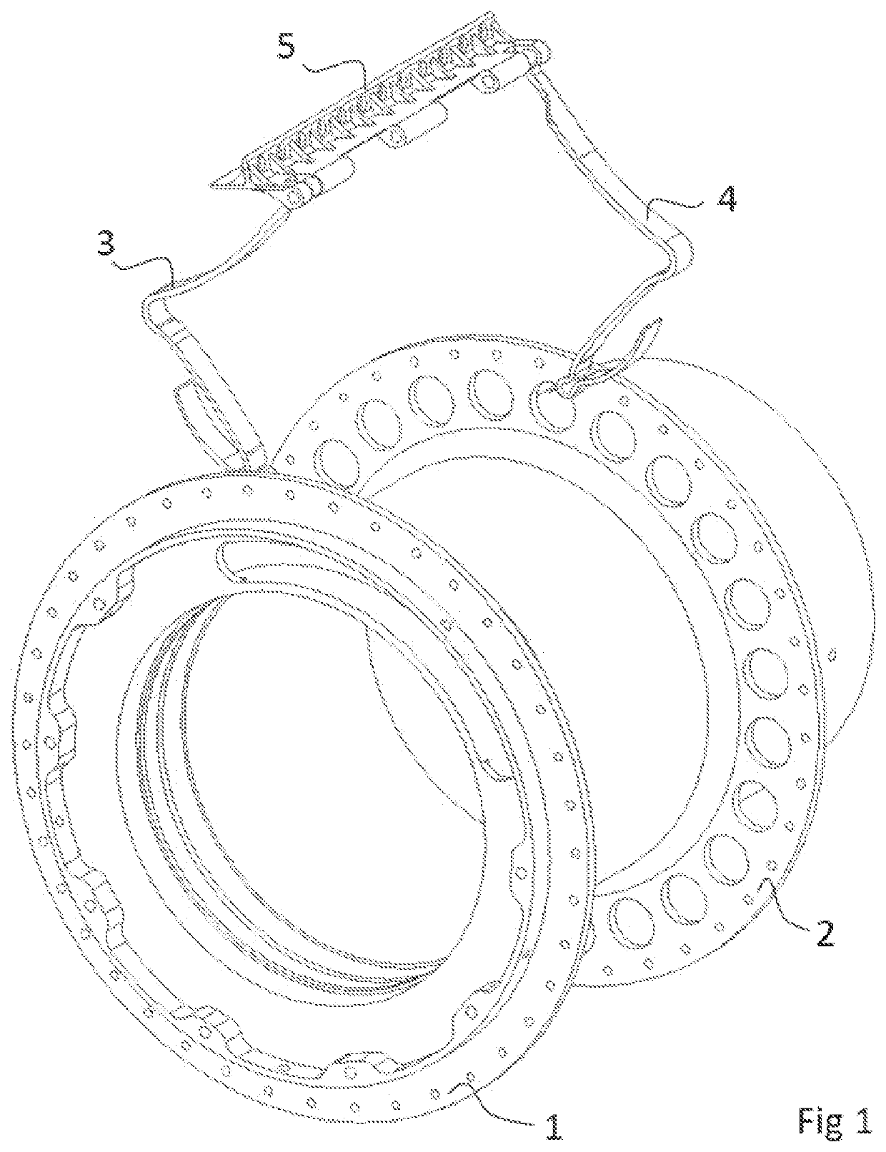
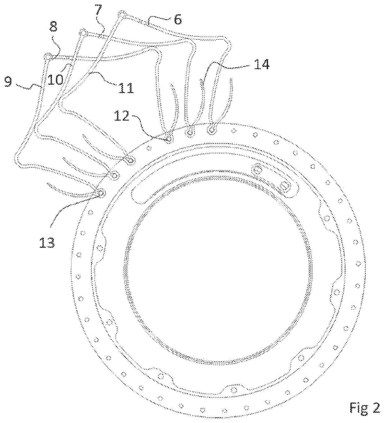
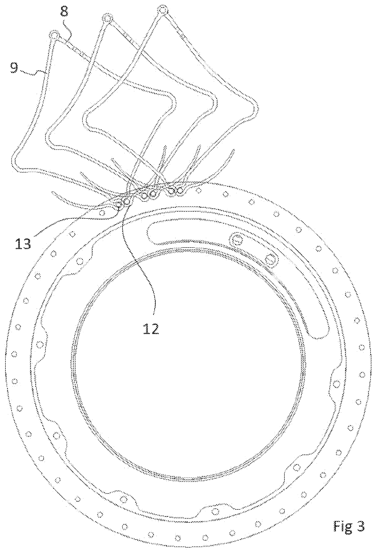
[0034]Hereinafter, an embodiment of a non-pneumatic tire according to the present invention will be described with reference to FIGS. 1 to 11. FIG. 1 presents the two split hubs of the wheel, split hub 1 and split hub 2, on each one of which a leaf spring 3 and 4 respectively is mounted on one of a plurality of holes of their periphery, by means of a mounting rod. The springs are free to rotate around their mounting rods. Both springs are shown connected to a single tile 5, via also a freely rotating joint that also serves as free rotating joint connecting the tile with its adjacent tiles, thus forming a circular multi-tile caterpillar chain, representing the part of the wheel that enters in contact with the ground. The relative angle between the two split hubs can be modified, in a way to bring closer the mounting points of each spring on their respective hub and also decrease the distance of the concave sections of each of the two springs 3 and 4. To better appreciate the effects ...


PUM


Abstract

A variable compliance non-pneumatic wheel which comprises a stationary tubular body (32) attached to the vehicle chassis. A tubular member is freely rotatable relative to the stationary tubular body and has a series of peripheral mounting rods (12, 13) on sides of the wheel. A plurality of interconnected and freely rotating caterpillar-like tiles (5), which are in contact with the ground during wheel operation, are coupled to the outer periphery of the wheel. A plurality of connecting spring members, (3, 4, 6, 7, 8, 9, 10, 11), each connecting a specific mounting rod on a side of the hub (1, 2) are configured to connect the tiles (5) to the hub. The tubular member is split in two parts (1, 2) which are each free to rotate relative to one another. Each part carries approximately half number of mounting rods and connecting springs on a respective side of the wheel.

Description

1. FIELD OF INVENTION[0001]The present invention relates to a non-pneumatic tire that can be used without filling it with pressurized air, with the capacity to alter its flexibility during operation as well as to measure the torque generated by or submitted to the wheel axis during operation.2. DESCRIPTION OF RELATED ART[0002]U.S. Pat. No. 6,170,544 B1 Hottebart Jan. 9,2001 refers to a Non-Pneumatic Deformable Wheel[0003]US 2017 / 0120671 A1 Miles et al. May 4, 2017 refers to Non-Pneumatic Tire with Partially Compliant Hub[0004]US 2018 / 0072095 A1 Anderfaas et al. Mar. 15, 2018 refers to Variable Compliance Wheel[0005]U.S. Pat. No. 8,950,451 B2 Akihiko Abe Feb. 10, 2015 refers to Non-Pneumatic Tire[0006]US 20020096237 A1 Buhroe et al. Jul. 25, 2002 refers to Compliant rim wheel and assembly[0007]US 2009 / 0211675 A1 Louden B. Aug. 27, 2009 refers to Non-Pneumatic Tyre Assembly[0008]US 2014 / 0110024 A1 Anderfaas et al. Apr. 24, 2014 refers to Variable Compliance Wheel[0009]US 2016 / 0193876 ...

Claims


Application Information

Patent Timeline
IPC IPC(8): B60B19/04B60B9/02B60B27/02B60B25/00B60C7/06B60C7/14B60C7/18
CPCB60B19/04B60B9/02B60B27/02B60B2900/351B60C7/06B60C7/143B60C7/18B60B25/002B60B9/26B60B2900/721B60C7/14B60C7/24B60C7/16B60B9/04
Inventor PAPANTONIOU, VASSILIOS
Owner HTR SA
Why Eureka
Try Eureka