Improved method for manufacturing a rotor

a manufacturing method and a technology for rotors, applied in the direction of manufacturing stators/rotor bodies, magnetic circuit rotating parts, magnetic circuit shapes/forms/construction, etc., can solve problems such as failure of generators, and achieve the effects of improving mechanical and material properties, simplifying the manufacturing method, and more even loading of sleeves

Pending Publication Date: 2022-06-16
SAFRAN ELECTRICAL & POWER
View PDF0 Cites 3 Cited by
  • Summary
  • Abstract
  • Description
  • Claims
  • Application Information

AI Technical Summary

Benefits of technology

[0015]Without wishing to be bound by theory, the inventors believe that both problems are due to compression of the inner layers by the tightly-wound outer layers during the wrapping and curing of the sleeve which causes fibres in the inner layers to move radially inward, thereby reducing the pre-stress of the inner layers of the resulting cured sleeve. This reduced pre-stress lowers the compressive force applied by the sleeve to the magnets on the rotor, resulting in an increased risk of magnet lift-off from the rotor surface during operation. The reduced pre-stress in the inner layers can also lead to a reduction in the share of the overall retention force of the sleeve which is borne by the inner layers. This under-utilisation of the inner layers leads to an increase in loading on the outer layers, resulting in the possibility of failure of the outer layers and, shortly after, the entire sleeve.
[0034]The elongate fibres and the curable matrix may be provided as a pre-impregnated fibrous material. This has the advantage of providing a simplified method of manufacture. The elongate fibres may comprise carbon fibre such that the composite sleeve is a carbon-fibre reinforced composite sleeve. This has the advantage of providing a sleeve with improved mechanical and material properties.

Problems solved by technology

If the magnets are not held in place by some form of mechanical support, they can lift off from the rotor body, which can result in failure of the generator.

Method used


Image

  • Improved method for manufacturing a rotor
  • Improved method for manufacturing a rotor
  • Improved method for manufacturing a rotor

Examples


Embodiment Construction

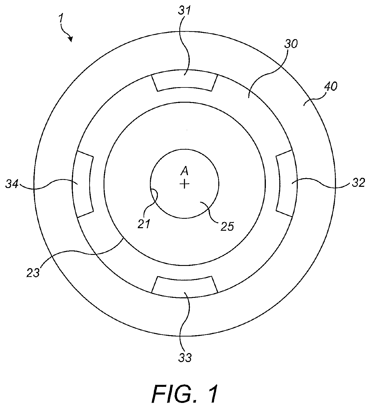
[0044]FIG. 1 shows a rotor 1 which has been being manufactured according to an embodiment of the present invention. The rotor 1 may have mechanical properties, materials properties and / or one or more visual indications which are indicative of having been made by this method. The rotor 1 may also have a composite fibre arrangement and / or microstructure indicative of having been made by this method.

[0045]The illustration provided in FIG. 1 does not highlight the differences between the present invention and known methods. These differences will be explained in detail in relation to FIG. 5.

[0046]As shown in FIG. 1, the rotor 1 comprises a rotor body 20, a magnet layer 30, and a sleeve 40.

[0047]The rotor body 20 is configured to support at least one magnet, which may be provided in a magnet layer 30 as shown in FIG. 1. The rotor body 20 is configured to translate a driving force from a driving means to rotate the magnet layer 30, so as to generate a moving magnetic field. The rotor body...


PUM


Abstract

A method of manufacturing a rotor for a generator of an aircraft engine. The method includes providing a rotor body; mounting at least one magnet on the rotor body; wrapping a tow around the rotor body and the at least one magnet to form a wrapped tow having a plurality of layers overlaid in the radial direction; and curing the wrapped tow to form at least a part of a fibre-reinforced composite sleeve configured to retain the at least one magnet on the rotor body. The step of wrapping includes applying a controlled tension to the tow during wrapping. The controlled tension is varied according to the radial position of the layer being wrapped.

Description

TECHNICAL FIELD[0001]The present invention relates to an improved method for manufacturing a rotor for a generator of an aircraft engine. The present invention also relates to a rotor for a generator of an aircraft engine manufactured according to such a method and to a generator of an aircraft engine and an aircraft propulsion unit comprising such a rotor.BACKGROUND OF THE INVENTION[0002]As will be understood by a person skilled in the design of generators, permanent magnet generators often include rotors with surface-mounted magnets, configured to induce electric fields in the windings of a corresponding stator. In high-speed electrical generators, the magnets can be exposed to extreme centripetal forces as they rotate. Factors such as the rotation speed of the rotor, the diameter of the rotor and the weight of the magnets can influence these centripetal forces. If the magnets are not held in place by some form of mechanical support, they can lift off from the rotor body, which ca...

Claims


Application Information

Patent Timeline
Patent Type & Authority Applications(United States)
IPC IPC(8): H02K1/28H02K1/278H02K1/04H02K15/03H02K15/12
CPCH02K1/28H02K1/278H02K15/12H02K15/03H02K1/04H02K2213/03H02K21/14
Inventor FLOWER, PAUL DAVIDURIONDO, ADRIAN
Owner SAFRAN ELECTRICAL & POWER
Why Eureka
Try Eureka