
Temperature compensation circuit in a voltage measurement

Pending Publication Date: 2022-06-23
BEAMEX
View PDF3 Cites 0 Cited by
  • Summary
  • Abstract
  • Description
  • Claims
  • Application Information

AI Technical Summary

Benefits of technology

The invention is about a way to determine a large voltage value without actually measuring it. The method involves using two voltage dividers with large and small resistors, and measuring the voltage across the small resistor. By calculating the transfer ratio of the voltage divider in a certain temperature, a "substantially large voltage value" can be calculated based on the measured voltage and the transfer ratio. The technical effect of this invention is to provide a more efficient and accurate way to measure large voltages without the need for a direct measurement.

Problems solved by technology

Therefore, there are measurement errors based on varying temperature values in a measurement configuration which involves at least one resistor, or other temperature sensitive component.
This has the problem of the accuracy in reaching the desired temperature, and also in selecting the right measurement time when the temperature of the resistor (or a respective temperature dependent element) has actually reached a steady state (i.e. a constant “inner” temperature).
A defect of this simple method is that it assumes that the temperature-dependency is a linearly affecting parameter e.g. on the resistance, i.e. the temperature coefficient is constant for any two temperatures.
This might not be true in all practical situations.
The drawbacks for such an oven are that the stabilization time is long which means that practicality weakens and quick measurements are not possible to be obtained.
Also, the constant temperature oven requires additional supply power which can be tricky in some measurement locations e.g. in a factory.

Method used


Image

  • Temperature compensation circuit in a voltage measurement

Examples


Embodiment Construction

[0027]The present invention discloses an apparatus and method for temperature compensation within a voltage measurement of a substantially large voltage. Also a computer program and a computer program product are aspects of the same invention.

[0028]The present invention is based on continuous, real-time compensation between similarly behaving electrical components.

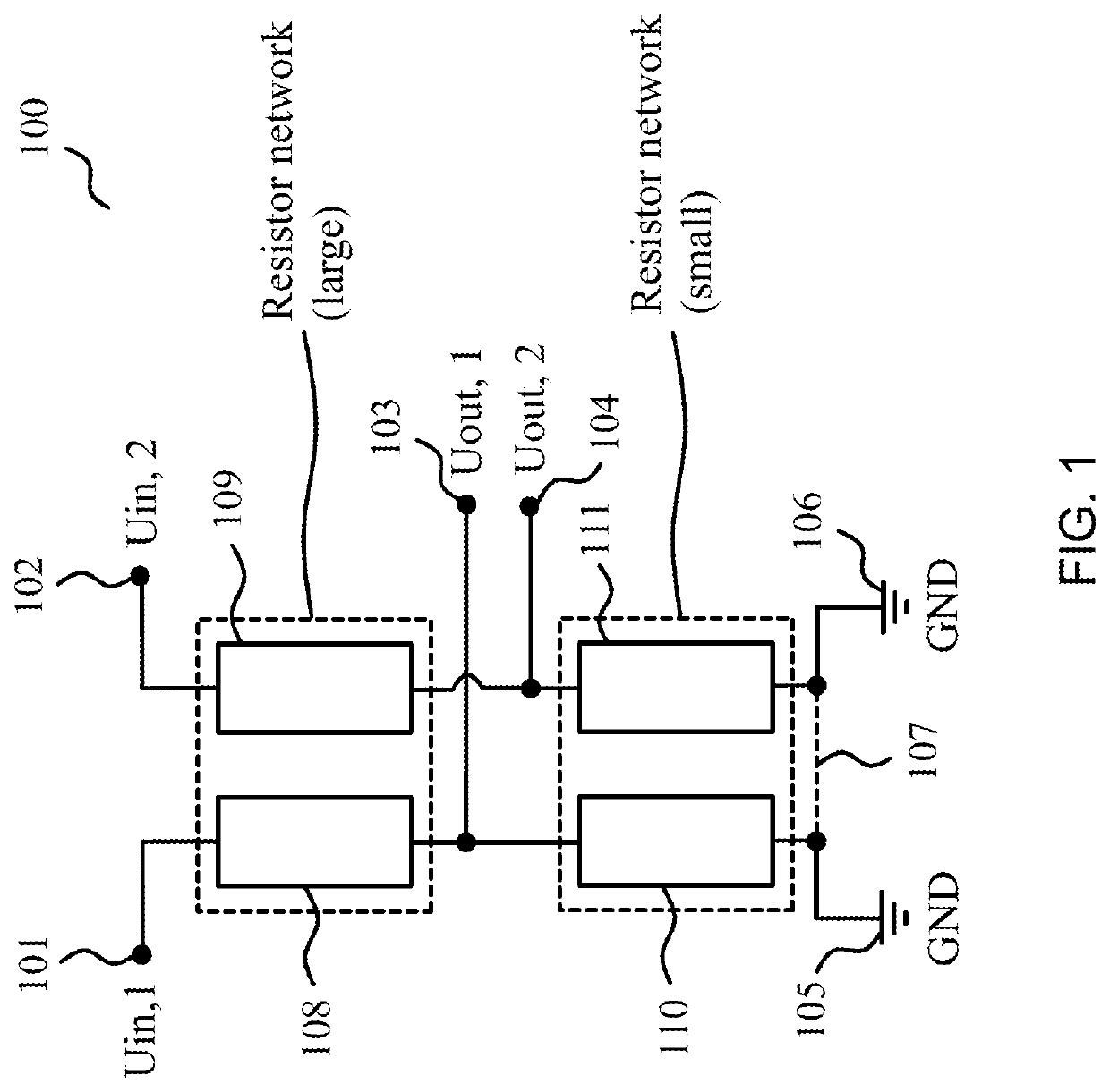
[0029]The starting point of the present invention is that a relatively high voltage is desired to be accurately measured. This process may happen in cold or warm temperatures, ranging from −30 . . . +50° C. for example. In the present invention, a voltage division principle can be applied in a form of a voltage divider circuit. This is exemplified in a circuit diagram shown in FIG. 1.

[0030]The circuit 100 in this embodiment comprises two main parts: a large resistor network 108, 109 comprising large resistances, and a small resistor network 110, 111 comprising small resistances. The voltage Uin, 1 101 is an unknown, large ...


PUM


Abstract

A method of determining a high voltage value without measuring the high voltage value directly, in varying possible temperatures. An apparatus includes two voltage divider circuits (108, 110; 109, 111), wherein the second circuit (i.e. a reference circuit 109, 111) is provided with a smaller reference input voltage (102). The transfer ratio can be obtained from the reference circuit (109, 111) through voltage measurements, and deduced into a transfer ratio of another circuit (108, 110), no matter the ambient temperature value. When measuring a divided voltage value (103) of one circuit (108, 110), the desired high voltage value (101) can be calculated, no matter what the ambient temperature is.

Description

CROSS-REFERENCE TO RELATED APPLICATIONS[0001]This application claims priority benefit of Serial No. 20206363, filed Dec. 22, 2020 in Finland, and which application is incorporated herein by reference. To the extent appropriate, a claim of priority is made to the above-disclosed applications.FIELD OF THE INVENTION[0002]The present invention relates to processes involving voltage measurements where a changing temperature is affecting the measurements, and where the measured voltage is relatively large.BACKGROUND OF THE INVENTION[0003]Voltage measurements for large voltages may be performed with a dedicated voltage meter but because of a large magnitude of the voltage, it is more practical to convert a high voltage to a smaller voltage at first. This operation may be performed by a transformer. Also, there are voltage dividing circuits available which are based on a resistor network. The voltage loss over a single resistor is smaller than over a series-connected group of resistors, whe...

Claims


Application Information

Patent Timeline
IPC IPC(8): G01R19/32G01R19/25G01R15/04
CPCG01R19/32G01R15/04G01R19/2506G01R1/44G01R19/0084G01R17/00
Inventor KETONEN, HANNU
Owner BEAMEX
Features
  • Generate Ideas
  • Intellectual Property
  • Life Sciences
  • Materials
  • Tech Scout
  • Unparalleled Data Quality
  • Higher Quality Content
  • 60% Fewer Hallucinations
Learn More