
A device and a method for measurements by raman spectroscopy

a raman spectroscopy and measurement method technology, applied in the direction of optical radiation measurement, instruments, spectrometry/spectrophotometry/monochromators, etc., can solve the problems of high laser power density used in raman spectroscopy, and reducing the size of the actual sampling area

Active Publication Date: 2022-06-30
SERSTECH
View PDF7 Cites 1 Cited by
  • Summary
  • Abstract
  • Description
  • Claims
  • Application Information

AI Technical Summary

Benefits of technology

The device described in the patent vibrates or moves the holder in a way that creates hot spots, which help to sample the substance being tested. This results in a larger area being tested, and a stronger signal being obtained.

Problems solved by technology

A small focus spot is desired to achieve high sensitivity, but this also reduces the size of the actual sampling area, which is an issue for non-uniform or non-homogenous samples.
Further, street drugs, such as cocaine and heroin, are often mixed with other substances for filling-up a delivery package, hence identification of included components by Raman spectroscopy can be difficult due to fluorescence from interferent components.
The high laser power density used in Raman spectroscopy provides problems.
It is common to illuminate small areas of a sample in Raman spectroscopy and the high laser power density can lead to massive heat development which may severely damage the sample.
Exposing the sample for a large amount of energy could also lead to other dangers, e.g. in the case of potentially explosive substances.
Another problem at detection of a substance when mixed with different components of a composition is that the characteristic spectra of the substance is hidden behind peaks from interfering components of the composition.

Method used


Image

  • A device and a method for measurements by raman spectroscopy
  • A device and a method for measurements by raman spectroscopy
  • A device and a method for measurements by raman spectroscopy

Examples


Embodiment Construction

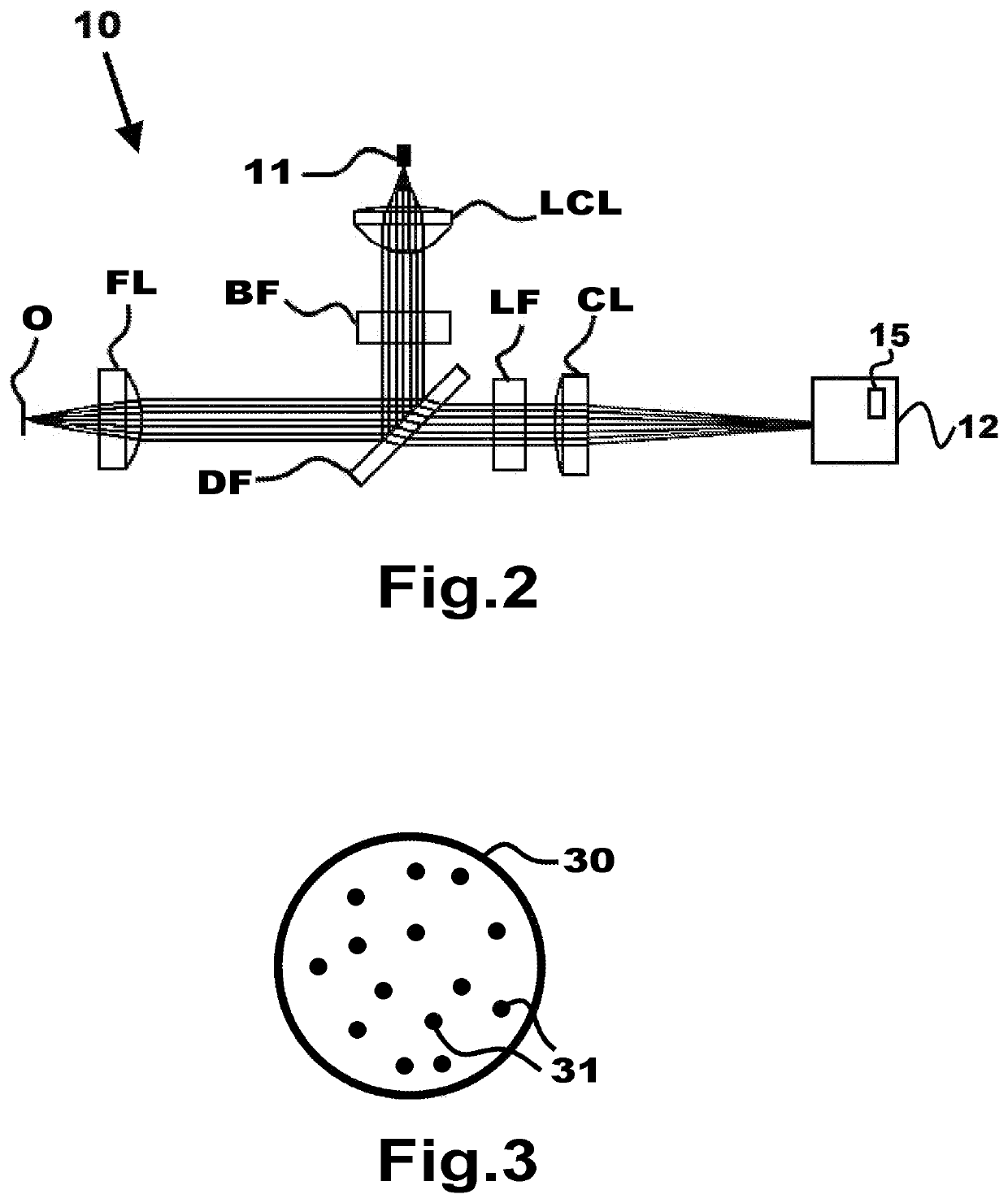
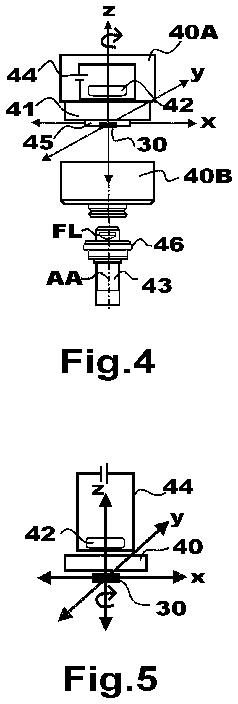
[0054]Specific embodiments of the invention will now be described with reference to the accompanying drawings. This invention may be embodied in many different forms and should not be construed as limited to the embodiments set forth herein; these embodiments are provided so that this disclosure will be thorough and complete, and will fully convey the scope of the invention for those skilled in the art. The terminology used in the detailed description of the embodiments illustrated in the accompanying drawings is not intended to be limiting of the invention.

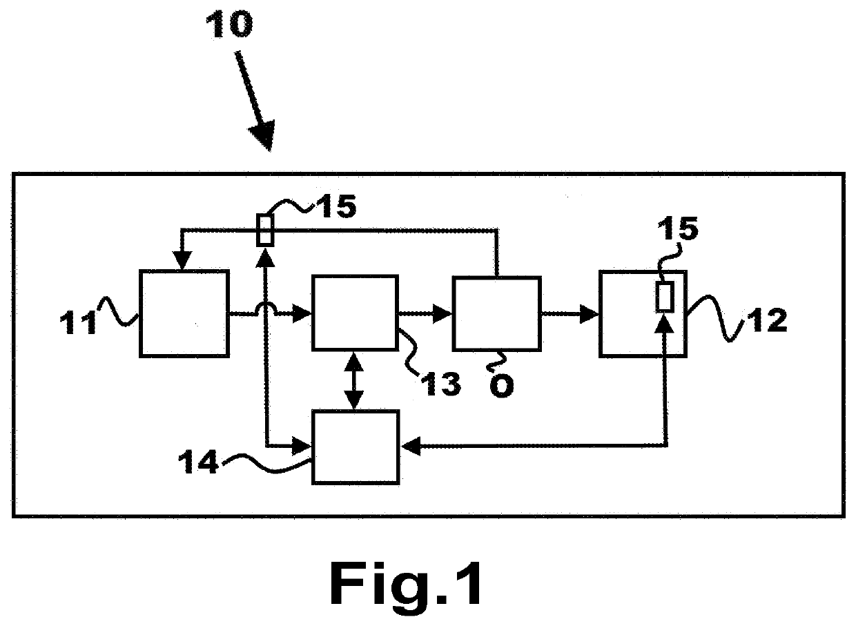
[0055]FIG. 1 is a schematic block diagram illustrating a Raman spectroscopy system 10 for analysing inelastic scattered light from an object O. In this disclosure the terms sample and object may be used interchangeably unless explicitly stated otherwise. The system 10 comprises an electromagnetic radiation source 11, a spectrograph unit 12, a focusing lens 13, a control unit 14, and a detector 15.

[0056]The electromagnetic radiati...


PUM


Abstract

A device for detection of a substance by Raman spectroscopy comprises a holder (40) with an area (41) adapted for receiving a sample of the substance and a vibration engine (42). The vibration engine (42) is configured to move the holder (40) in a three-dimensional motion when the area (41) with the substance is arranged in front of a focusing lens (FL) of the spectrometer to provide a large actual sampling area and hence to achieve a strong signal at detection. The device comprises a SERS surface (30) arranged at the area (41) of the holder (40) for adsorption of the sample of the substance. A method for detection of a substance by use of the device is also presented.

Description

TECHNICAL FIELD[0001]The present invention relates generally to the field of spectroscopy. More particularly, it relates to a device configured for measurements by a Raman spectroscopy system.[0002]The invention also relates to a method for measurements by use of the device with a Raman spectroscopy system.BACKGROUND OF THE INVENTION[0003]Raman spectroscopy is a certain spectroscopy technique that enables observation of vibrational, rotational, and other low frequency modes in a system. Raman spectroscopy is common practice e.g. in the field of chemistry in order to provide a fingerprint by which different molecules may be identified.[0004]Raman spectroscopy provides information about molecular vibrations that may be used for identification or quantification of a material which a sample is made up of. The sample is illuminated by an electromagnetic radiation source such as a laser or LED having monochromatic light. The light incident on the sample is scattered, absorbed or transmitt...

Claims


Application Information

Patent Timeline
IPC IPC(8): G01N21/65G01J3/02G01J3/44G01N33/94
CPCG01N21/658G01J3/0272G01J3/0208G01J3/44G01N33/94G01J3/0202G01N33/946G01N33/493G01N2201/0221G01J3/02G01J3/0256G01N21/17G01N21/1717G01N21/554G01N2021/4709
Inventor SZYBEK, KATJABILLSTEN, PETERDIEDRICHS, JOHAN
Owner SERSTECH
Learn More