Water treatment system and water treatment method

a water treatment system and water treatment technology, applied in water treatment multi-stage treatments, membranes, reverse osmosis, etc., to achieve the effect of efficient water treatmen

Pending Publication Date: 2022-07-07
ORGANO CORP
View PDF0 Cites 0 Cited by
  • Summary
  • Abstract
  • Description
  • Claims
  • Application Information

AI Technical Summary

Benefits of technology

[0075]According to the water treatment system and the water treatment method of the present invention, scale generated on the surface of an RO membrane can be washed and removed without stopping an RO membrane treatment of raw water and without discharging the water provided for washing out of the system. As a result, water treatment can be carried out efficiently.

Problems solved by technology

In a water treatment using a reverse osmosis membrane (RO membrane), scaling that clogs the RO membrane due to precipitation of dissolved salts and the like in the water to be treated on the surface of a concentrated water side of the RO membrane causes a problem.

Method used


Image

  • Water treatment system and water treatment method
  • Water treatment system and water treatment method
  • Water treatment system and water treatment method

Examples


example 1

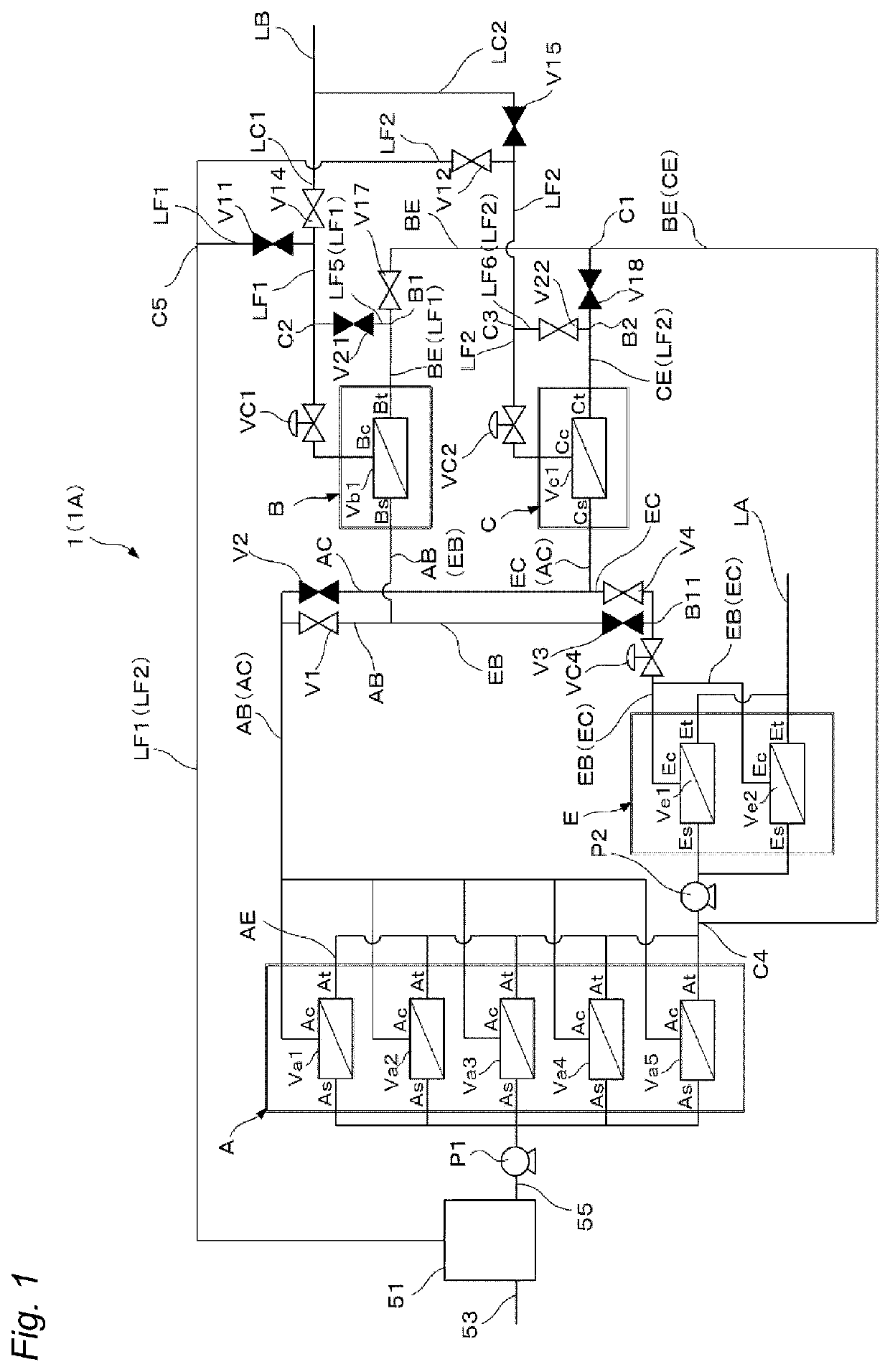
[0285]In Example 1, a raw water having a Ca concentration of 20 ppm, a silica concentration of 15 ppm, an electrical conductivity of 200 μS / cm and pH=8.5 was subjected to an RO membrane treatment using the water treatment system 1A illustrated in FIG. 1. Regarding the RO membranes, ES20-D8 (trade name) manufactured by Nitto Denko Corp. was used. The recovery rate of the RO membrane device A was set to 50%, the recovery rate of the RO membrane device B was set to 50%, the recovery rate of the RO membrane device E was set to 90%, and the overall recovery rate of the system was set to 73%. The concentrated water from the RO membrane device A was supplied to the RO membrane device B, and the concentrated water from the RO membrane device E was supplied to the RO membrane device C. The permeated water from the RO membrane device B was caused to flow to the supply side of the RO membrane device E. The recovery rate of the RO membrane device C was set to 10% or less. The permeated water an...

example 2

[0286]In Example 2, the water treatment system 1A illustrated in FIG. 1 was used, hydrochloric acid was injected into the concentrated water from the RO membrane device E, and the pH of the concentrated water was adjusted to 5.5. Then, after the first connection line was switched to the second connection line, this concentrated water was supplied to the RO membrane device B, and the RO membrane device B was washed. Except for those, water flow was carried out under conditions similar to those of Example 1. That is, after a lapse of 200 h from the initiation of washing of the RO membrane device B, the line was switched again (switched from the second connection line to the first connection line), and a comparison was made between the amount of permeated water J of the RO membrane device B at the time of causing the concentrated water from the RO membrane device A to flow to the RO membrane device B and the initial (at the time of initiating operation) amount of permeated water J0 of ...

example 3

[0287]pH meters were installed at the supplied water and the concentrated water from the RO membrane device B, and the difference in pH was measured. PID control was performed from the difference between this difference in pH and the ideal pH difference at every lapse of washing time, and the injection amount of hydrochloric acid was controlled. Except for those, water flow was carried out under conditions similar to those of Example 2. That is, after a lapse of 200 h from the initiation of washing of the RO membrane device B, the line was switched again (switched from the second connection line to the first connection line), and a comparison was made between the amount of permeated water J of the RO membrane device B at the time of causing the concentrated water from the RO membrane device A to flow to the RO membrane device B and the initial (at the time of initiating operation) amount of permeated water J0 of the RO membrane device B. Furthermore, the system recovery rate was cal...


PUM

PropertyMeasurementUnit
electrical conductivityaaaaaaaaaa
pressureaaaaaaaaaa
electrical conductivityaaaaaaaaaa

Abstract

A water treatment system including: a reverse osmosis membrane device A for treating a water to be treated; a reverse osmosis membrane device E for treating permeated water from device A; a reverse osmosis membrane device B for treating concentrated water from device A or E; a reverse osmosis membrane device C for treating concentrated water from device E or A; and each of water flow lines through which the concentrated water and permeated water from devices A to E respectively flow downstream, wherein the connections of each of the water flow lines are switchable so that while the concentrated water from device E flows to device B to wash device B, the concentrated water from device A is treatable by device C, and while the concentrated water from device E flows to device C to wash device C, the concentrated water from device A is treatable by device B.

Description

FIELD OF THE INVENTION[0001]The present invention relates to a water treatment system and a water treatment method.BACKGROUND OF THE INVENTION[0002]In a water treatment using a reverse osmosis membrane (RO membrane), scaling that clogs the RO membrane due to precipitation of dissolved salts and the like in the water to be treated on the surface of a concentrated water side of the RO membrane causes a problem. As a technology for suppressing scaling, it is widely known to add a pH adjusting agent to the water to be treated or to add a scale dispersant that suppresses scale generation (see, for example, Patent Literature 1).[0003]On the other hand, a method of washing the scale generated on the RO membrane surface by utilizing RO membrane-permeated water is known. For example, Patent Literature 2 discloses that backwashing is performed by causing permeated water to flow from the permeated water side of an RO membrane in order to suppress silica scale. Furthermore, Patent Literature 3 ...

Claims


Application Information

Patent Timeline
Patent Type & Authority Applications(United States)
IPC IPC(8): C02F1/44B01D61/08B01D61/12B01D65/08B01D61/02
CPCC02F1/441C02F2209/05B01D61/12B01D65/08B01D61/022C02F2301/08C02F2303/16C02F2303/22B01D2317/06B01D2317/04B01D2317/022B01D2317/025B01D2321/16B01D2321/40C02F2209/006C02F2209/03C02F2209/06B01D61/08C02F2209/40C02F2209/005C02F1/008B01D61/025B01D2317/02B01D65/02Y02A20/131B01D61/026
Inventor NAKAMURA, YUKI
Owner ORGANO CORP
Why Eureka
Try Eureka