
Validation of a signal from a crankshaft sensor

a crankshaft sensor and signal validation technology, applied in the direction of machines/engines, electric control, instruments, etc., can solve the problems of insufficient precision of position determination, faulty signal generation of crankshaft sensors, and no longer optimal operation of engines

Active Publication Date: 2022-07-21
VITESCO TECH GERMANY GMBH
View PDF13 Cites 2 Cited by
  • Summary
  • Abstract
  • Description
  • Claims
  • Application Information

AI Technical Summary

Benefits of technology

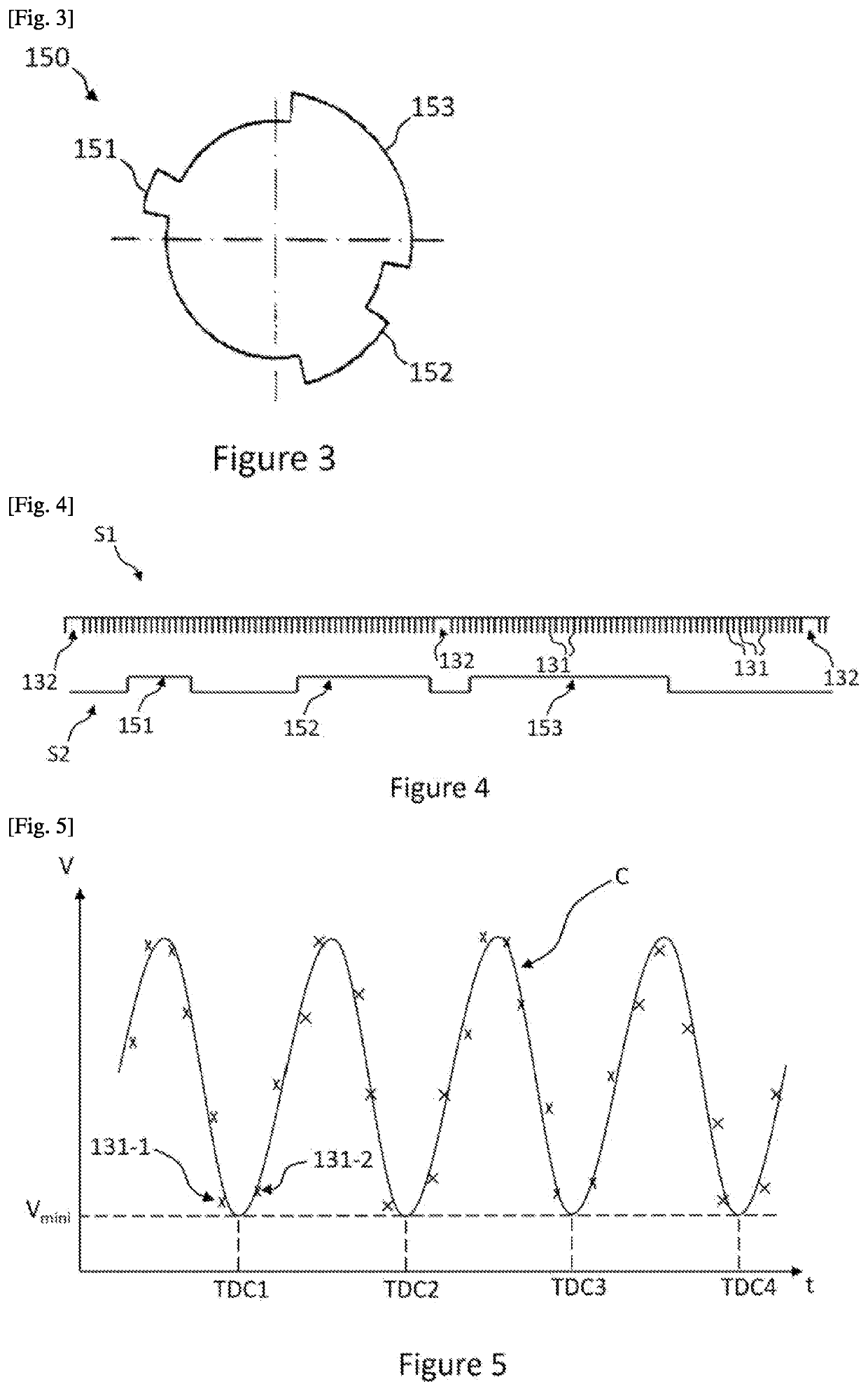
The invention proposes a method to quickly determine the end of a transient failure of a crankshaft sensor in a reliable manner. The method involves comparing the angular positions of the minimum speed in the vicinity of the combustion top dead centers of the crankshaft with corresponding reference values, allowing the computer to quickly return to the normal operating mode. The method is effective regardless of the engine speed and automatically verifies the synchronization of the engine due to the distinct position of the toothed wheel of the crankshaft. The minimum rotation speed of each combustion top dead center can be easily determined by analyzing a modeled curve of the speed of the crankshaft. The method also includes a step of computing the difference between the determined rotation speed of the crankshaft and a speed threshold to detect a failure. The speed curve is modeled by a parabola. Overall, the invention enables a quick and reliable determination of the end of a transient failure of the crankshaft sensor.

Problems solved by technology

However, the crankshaft sensor can generate a faulty signal, in particular by detecting a higher or lower number of teeth of the crankshaft target between the two signatures, for example, one tooth more or one tooth less.
However, the target mounted on the camshaft comprises a small number of teeth; the position determined thus is not very precise.
The operation of the engine is then no longer optimal, which in particular increases the discharges of polluting gases from the engine.
However, such a solution is time consuming.
In other words, the duration during which the engine incorrectly operates in a degraded mode is significant.

Method used


Image

  • Validation of a signal from a crankshaft sensor
  • Validation of a signal from a crankshaft sensor

Examples


Embodiment Construction

[0036]An aspect of the invention will be described hereafter in the light of implementation in a motor vehicle. However, any implementation in a different context, in particular for any vehicle comprising an internal combustion engine, for which the angular position needs to be determined, is also covered by an aspect of the present invention.

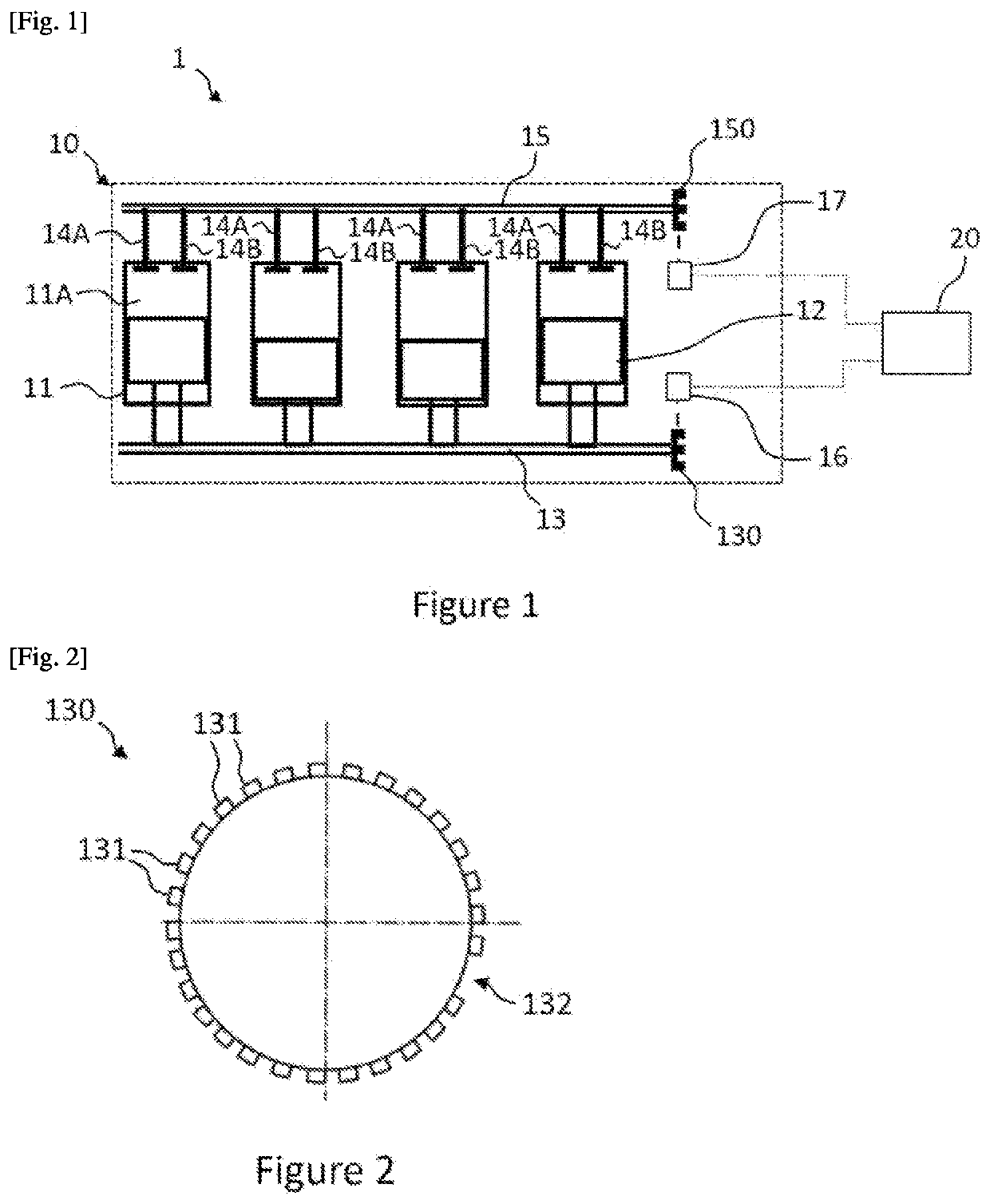
[0037]FIG. 1 schematically shows a side view of an internal combustion engine 10 of a motor vehicle 1. The vehicle 1 further comprises the engine 10, a computer 20.

[0038]The internal combustion engine 10 comprises, in this non-limiting example, four cylinders 11 each demarcating a combustion chamber 11A, in which a piston 12 slides, connected to a crankshaft 13 and the movement of which is driven by the compression and the expansion of the gases originating from the compression of an air and fuel mixture introduced into the combustion chambers 11A.

[0039]In this example, the engine 10 is of the four-stroke engine type. Furthermore, during operat...


PUM


Abstract

The invention relates to a method for switching between a degraded mode and a normal mode for establishing the angular position of an internal combustion engine (10) of a vehicle (1), the method comprising the steps of, in degraded mode, detecting the free space and the teeth of the toothed wheel (130) of the crankshaft (13) during the rotation of the crankshaft (13) from the signal generated by the crankshaft sensor (16), establishing the angular positions of the crankshaft (13) corresponding to the minimum rotation speeds of the top dead centres established, and switching to normal mode when, for each top dead centre, the deviation between the angular position of the crankshaft (13) and a reference position is less than a position threshold for at least one revolution of the crankshaft (13).

Description

CROSS REFERENCE TO RELATED APPLICATIONS[0001]This application is the U.S. National Phase Application of PCT International Application No. PCT / EP2020 / 065139, filed Jun. 2, 2020, which claims priority to French Patent Application No. 1906054, filed Jun. 7, 2019, the contents of such applications being incorporated by reference herein.FIELD OF THE INVENTION[0002]The invention relates to the field of fuel injection in an internal combustion engine and, more specifically, it relates to a method for managing the synchronization of an internal combustion engine. In particular, the aim of the invention is to enable a return to the normal operating mode of the engine after a transient failure of the signal originating from a crankshaft sensor has been detected. More specifically, the invention relates to a method for validating the elimination of a transient failure of the signal originating from a crankshaft sensor of an internal combustion engine of a vehicle.BACKGROUND OF THE INVENTION[00...

Claims


Application Information

Patent Timeline
Patent Type & Authority Applications(United States)
IPC IPC(8): F02D41/00F02D41/22
CPCF02D41/009F01L1/047F02D41/0097F02D41/222F02D2041/227F02D2200/101F02D2041/286G01P3/481F01L2820/042
Inventor ELOY, STÉPHANEGOUZENES, NORA
Owner VITESCO TECH GERMANY GMBH
Learn More