
Particle Sampling Systems and Methods for Robotic Controlled Manufacturing Barrier Systems

a technology of robotic control and manufacturing barrier, applied in the field of robotic sampling and counting system, can solve the problems of increasing the risk of particulate and biological contamination levels

Active Publication Date: 2022-07-28
PARTICLE MEASURING SYST
View PDF2 Cites 1 Cited by
  • Summary
  • Abstract
  • Description
  • Claims
  • Application Information

AI Technical Summary

Benefits of technology

The patent text describes systems and methods for using a robotic system to collect and analyze environmental samples in controlled environments, such as RABS and positive pressure isolator systems. These systems can be integrated with a sampler and / or analyzer for positioning, connecting, sampling, and analyzing the environment with minimal human contact, reducing the risk of contamination. The sampling head and base are designed to securely enclose the collection surface and can handle the particle sampling or counting device effectively without the need for human intervention. The systems can also include robotic sterilization of the environment or sampling components to further reduce or eliminate the risk of contamination. Overall, the patent text provides a way to safely and efficiently collect and analyze samples in controlled environments.

Problems solved by technology

Humans being present in such environments increases the risk of particulate and biological contamination levels.
However, many applications requiring controlled environments also require or utilize environmental sampling to ensure that viable and non-viable particles and / or organisms remain below the desired levels.

Method used


Image

  • Particle Sampling Systems and Methods for Robotic Controlled Manufacturing Barrier Systems
  • Particle Sampling Systems and Methods for Robotic Controlled Manufacturing Barrier Systems
  • Particle Sampling Systems and Methods for Robotic Controlled Manufacturing Barrier Systems

Examples


example 1

and Biological Contaminant Sampling or Counting Devices, or Viable / Non-Viable Particle Sampling Devices

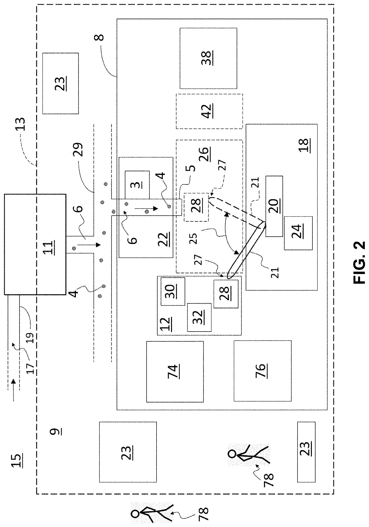
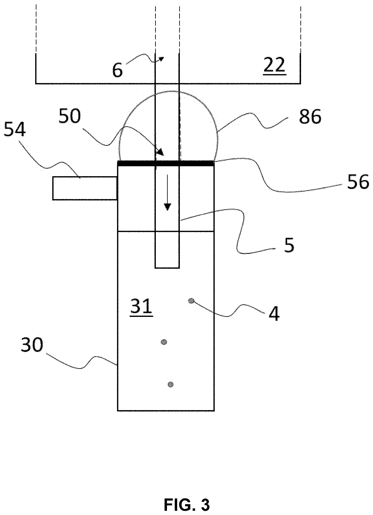
[0094]In an example, particle sampling or counting device (12) is an impactor (28). Impactor (28) may be any of the devices disclosed in U.S. patent application Ser. No. 14 / 338,615, which is incorporated by reference herein in its entirety. In another example, particle sampling or counting device (12) is an impinger (30). In yet another example, particle sampling or counting device (12) is configured for use with cyclone-based methods. In still another embodiment, the particle sampling or counting device (12) is an optical particle counter (32). In still another embodiment, the particle sampling or counting device (12) includes any combination of: impactor (28), impinger (30), optical particle counter (32), and device (12) configured for use with cyclone-based methods. In yet another embodiment, the particle sampling or counting device (12) includes each of: impactor (28), impinger...

example 2

ly Controlled Optical Particle Counter

[0126]The systems and methods described herein may incorporate an optical particle counter systems used in conjunction with robotic control systems, for example, to position the optical particle counter to receive fluid in order to characterize the fluid, including determining number, size or other characteristics of the particles contained in the fluid.

[0127]Optical particle counters are known in the art, for example, in U.S. Pat. No. 7,745,469, U.S. Pat. No. 7,916,29 and U.S. Pat. No. 8,154,724, which are each incorporated by reference in their entirety and specifically with regard to optical particle detection systems and methods.

[0128]FIG. 14 provides an example of an optical particle counter system. Fluid flows through a flow system 150 into a flow chamber 210. An optical source 220 projects a beam of electromagnetic radiation 221 (e.g., a laser) into the flow chamber 210, where the electromagnetic radiation 221 interacts with any particles...


PUM


Abstract

Provided herein are systems and methods allowing for automated sampling and / or analysis of controlled environments, for example, to determine the presence, quantity, size, concentration, viability, species or characteristics of particles within the environment. The described systems and methods may utilize robotics or automation or remove some or all of the collection or analysis steps that are traditionally performed by human operators. The methods and systems described herein are versatile and may be used with known particle sampling and analysis techniques and particle detection devices including, for example, optical particle counters, impingers and impactors.

Description

CROSS-REFERENCE TO RELATED APPLICATIONS[0001]This application is a continuation application of U.S. application Ser. No. 16 / 678,687, filed Nov. 8, 2019. U.S. application Ser. No. 16 / 678,687 claims the benefit of and priority to U.S. Provisional Patent Application Nos. 62 / 768,365 filed Nov. 16, 2018 and 62 / 831,343 filed Apr. 9, 2019. Each of the referenced applications are hereby incorporated by reference in their entireties to the extent not inconsistent herewith.BACKGROUND OF INVENTION[0002]This invention is in the field of manufacturing barrier systems. This invention relates generally to systems and methods for robotic sampling and counting systems for sampling particles from fluids in controlled environments.[0003]In sterile processing, aseptic manufacturing, and cleanroom environments in a number if industries such as pharmaceuticals, biopharmaceuticals, parenteral drugs and medical devices, and microfabrication among others, maintaining operations under stringent specification...

Claims


Application Information

Patent Timeline
Patent Type & Authority Applications(United States)
IPC IPC(8): G01N1/22G01N15/06G01N35/00
CPCG01N1/2247G01N15/0606G01N2015/0046G01N1/2202G01N2015/0693G01N35/0099G01N1/02G01N15/0205G01N15/1459G01N2001/021G01N2001/028G01N2001/2223G01N2001/2291G01N2015/1486G01N15/075
Inventor SCIALO, GIOVANNIRECCHIA, DAVIDE
Owner PARTICLE MEASURING SYST
Learn More