Automatic discharge setting

a centrifugal separator and automatic setting technology, applied in centrifuges, rotary centrifuges, etc., can solve the problems of difficult to determine whether the desired amount of discharge is actually being discharged from the bowl, the disadvantage of conventional discharge methods, and the loss of milk products

Pending Publication Date: 2022-08-11
TETRA LAVAL HLDG & FINANCE SA
View PDF0 Cites 0 Cited by
  • Summary
  • Abstract
  • Description
  • Claims
  • Application Information

AI Technical Summary

Benefits of technology

[0004]It is an object of the invention to at least partly overcome one or more limitations of the prior art. In particular, it is an object to provide a method for calibrating the centrifugal separator that enables automation of sediment discharging.
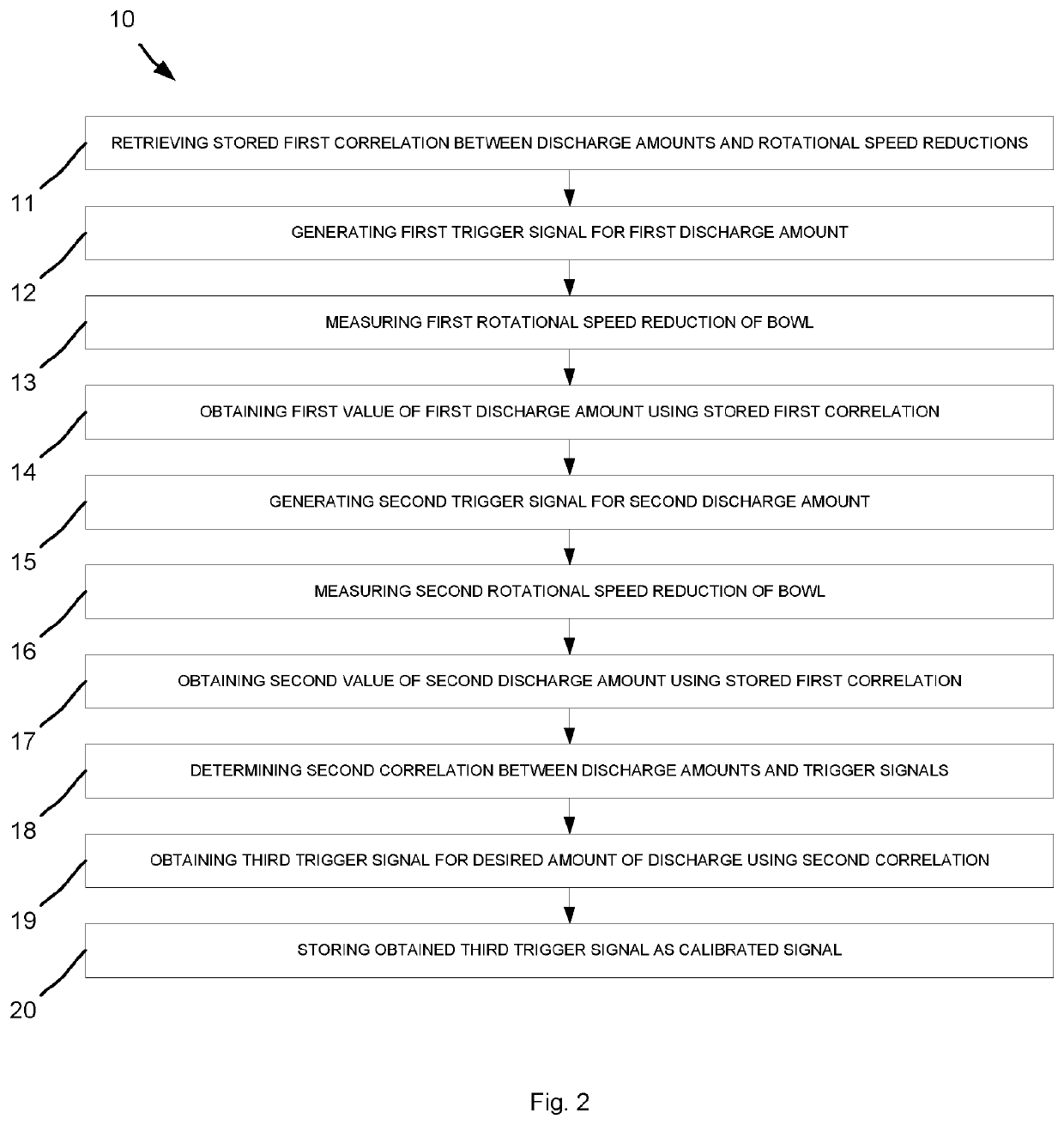
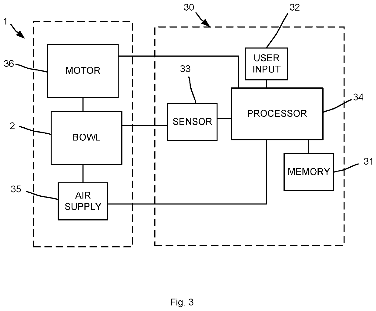
[0006]The method described herein is advantageous in eliminating the manual process of repeatedly measuring different discharge amounts. Predetermined data pertaining to the correlation or relationship between different amounts of discharge and rotational speed reductions for a particular separator type is stored. Using the stored data and the measured rotational speed reductions enables the amounts of discharges to be automatically determined based on the measured rotational speed reduction without manually measuring the discharge amount. The discharges are performed in response to trigger signals, such that the determined amounts of the discharges are then used to determine the correlation between the trigger signals and the amounts of the discharges. The trigger signals may correspond to any suitable system parameter or setting, such as an amount of air or water pressure, an amount of air or water flow, or an amount of time for a flow of air or water that is supplied to the centrifugal separator for performing the discharges. Using the determined correlation between the trigger signals and the discharge amounts enables a single parameter or setting in the system to be changed to obtain the desired discharge amount. The centrifugal separator may be calibrated and the discharge method may be automated using a processor and control system to perform the method.

Problems solved by technology

If a discharge is performed too quickly or too large of an amount of discharge is ejected, the milk product may be lost.
The desired amount of discharge is dependent on the size of the bowl, but determining whether the desired amount of discharge is actually being discharged from the bowl is difficult.
However, conventional discharge methods are disadvantageous due to the burdensome process of the manual trial and error method.

Method used


Image

  • Automatic discharge setting
  • Automatic discharge setting
  • Automatic discharge setting

Examples


Embodiment Construction

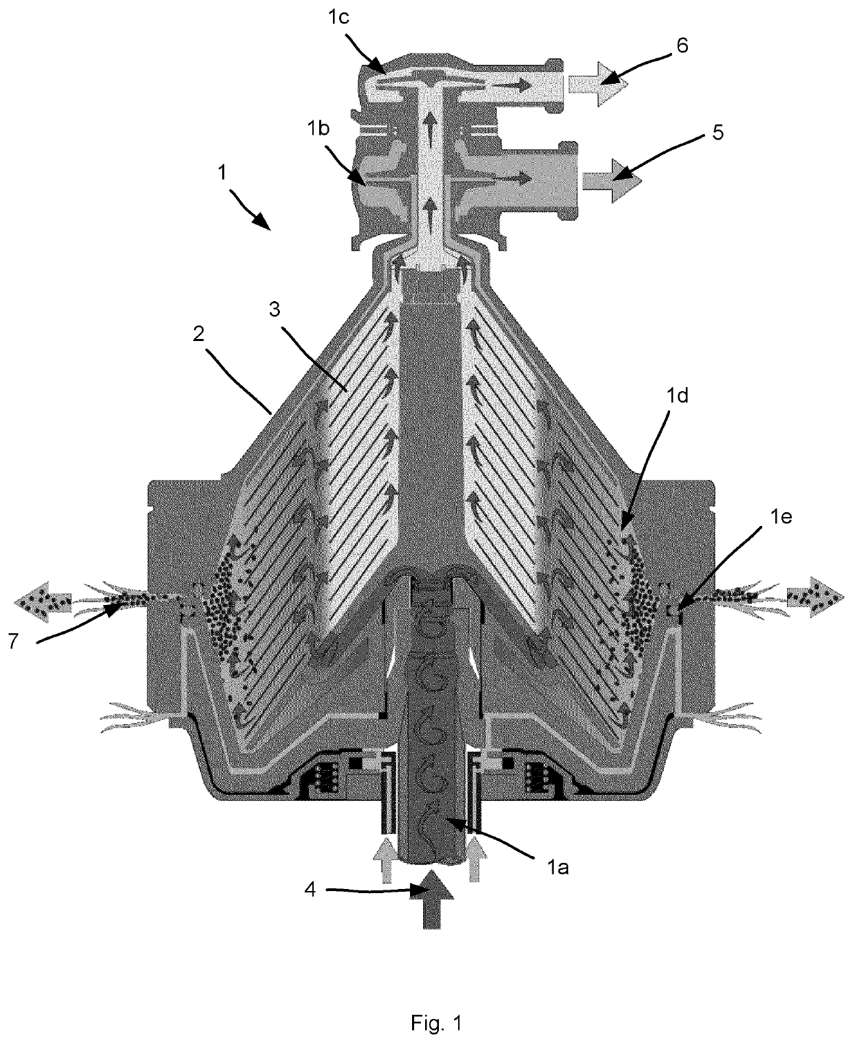
[0015]The method and system according to the present invention has particular application in centrifugal separators used in the production of milk products. More particularly, the method is used for a centrifugal separator that receives an intake of unseparated liquid food and produces multiple milk products, such as a heavy product phase and a light product phase.

[0016]The present invention pertains to a calibration method for discharging sediment from a centrifugal separator having a rotatable bowl that includes retrieving stored date representing a predetermined correlation between different amounts of discharges of the sediment phase and rotational speed reductions of the rotatable bowl due to the performed discharges for a particular centrifugal separator, generating trigger signals to discharge different amounts of the sediment, measuring the rotational speed reductions of the rotatable bowl that correspond to the performed discharges, obtaining values corresponding to the amo...


PUM


Abstract

A method of calibrating a centrifugal separator includes retrieving stored data representing a first correlation between different amounts of sediment discharges and rotational speed reductions of the rotatable bowl, generating trigger signals to discharge different amounts of sediment, measuring rotational speed reductions of the rotatable bowl that correspond to the discharges, obtaining values corresponding to the sediment discharges based on the rotational speed reductions and the first correlation, determining data representing a second correlation between the different sediment discharges and trigger signals based on the trigger signals and the values corresponding to the sediment discharges, and obtaining a trigger signal corresponding to a desired discharge amount based on the second correlation.

Description

TECHNICAL FIELD[0001]The invention relates to a method and system for calibrating a centrifugal separator used to separate an unseparated liquid food into different phases by centrifugal separation.TECHNICAL BACKGROUND[0002]Centrifugal separation is used in the production of milk. A centrifugal separator includes a rotatable bowl having a disc stack. An unseparated liquid food, such as the milk received from a cow, is supplied to the centrifugal separator for separation into multiple outputted milk products. By way of centrifugal force, sediment or sludge, e.g. straw, hairs, udder cells, white blood corpuscles (leucocytes), red blood corpuscles, bacteria, and other debris, and fat globules, e.g. cream, settles radially outwardly or inwardly in the separation channels of the bowl according to the relative density as compared with a continuous medium, such as a skim milk product. The high-density solid impurities of the sediment phase settle outwardly toward the periphery of the separ...

Claims


Application Information

Patent Timeline
Patent Type & Authority Applications(United States)
IPC IPC(8): B04B11/04B04B1/14
CPCB04B11/04B04B1/14
Inventor ÖLUND, ÅKEBYHMER, FREDRIK
Owner TETRA LAVAL HLDG & FINANCE SA
Why Eureka
Try Eureka