Eureka AIR delivers breakthrough ideas for toughest innovation challenges, trusted by R&D personnel around the world.

Anti-passivation, anti-blockage and efficiency-enhancing ultrasonic fuel cell

Pending Publication Date: 2022-08-11
PENG ZHIJUN
View PDF3 Cites 0 Cited by
  • Summary
  • Abstract
  • Description
  • Claims
  • Application Information

AI Technical Summary

Benefits of technology

The present invention provides an ultrasonic fuel cell that overcomes the disadvantages of prior art. The invention includes a membrane frame with a larger volume for grabbing, which is more convenient for robotic assembly and production. The reaction membrane is mounted on the membrane frame, and ultrasonic elements are installed in the membrane frame to directly act on the reaction membrane. This allows the reaction membrane to receive a better and more direct effect from the ultrasonic energy and reduces the loss of ultrasonic energy. The design of the membrane frame also improves the production efficiency of the fuel cell and reduces its manufacturing cost. Additionally, the invention provides an ultrasonic heating effect on the galvanic pile to prevent freezing and blockage under extremely cold environments, which ensures normal operation of the fuel cell. The invention also utilizes high-frequency ultrasonic vibration generated by the ultrasonic energy convertors to prevent impurities generated during fuel reaction process from depositing on and blocking the fluid channels, thereby improving the conversion efficiency of hydrogen to electricity, reducing the loss, improving energy conversion efficiency, and increasing the reliability of the fuel cell.

Problems solved by technology

However, during usage, the fluid channels on the bipolar plates, as well as the carbon paper / carbon cloths, catalyst sheet layers, and proton exchange membrane, etc., attached to the channels, are blocked and gradually passivated due to deposition of impurities during fuel reactions.
This undermines the efficiency of the conversion into electrical energy or even causes malfunctioning.
However, since the ultrasonic energy convertors are provided on the polar plates, the ultrasonic energy is only applied indirectly to the proton exchange membrane, the carbon paper / carbon cloths, and the catalyst sheet layers, leading to energy loss.

Method used


Image

  • Anti-passivation, anti-blockage and efficiency-enhancing ultrasonic fuel cell
  • Anti-passivation, anti-blockage and efficiency-enhancing ultrasonic fuel cell
  • Anti-passivation, anti-blockage and efficiency-enhancing ultrasonic fuel cell

Examples


Embodiment Construction

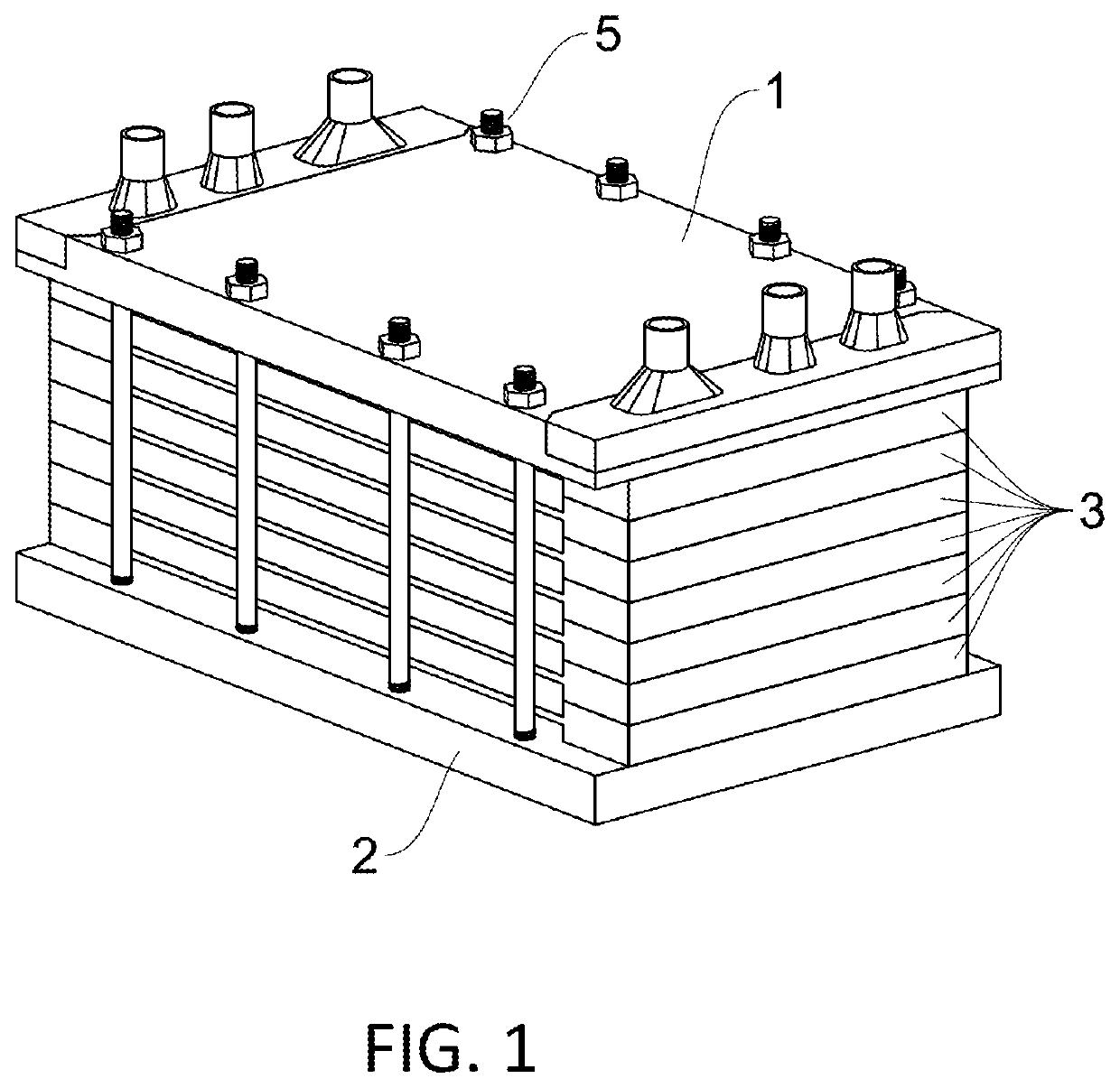
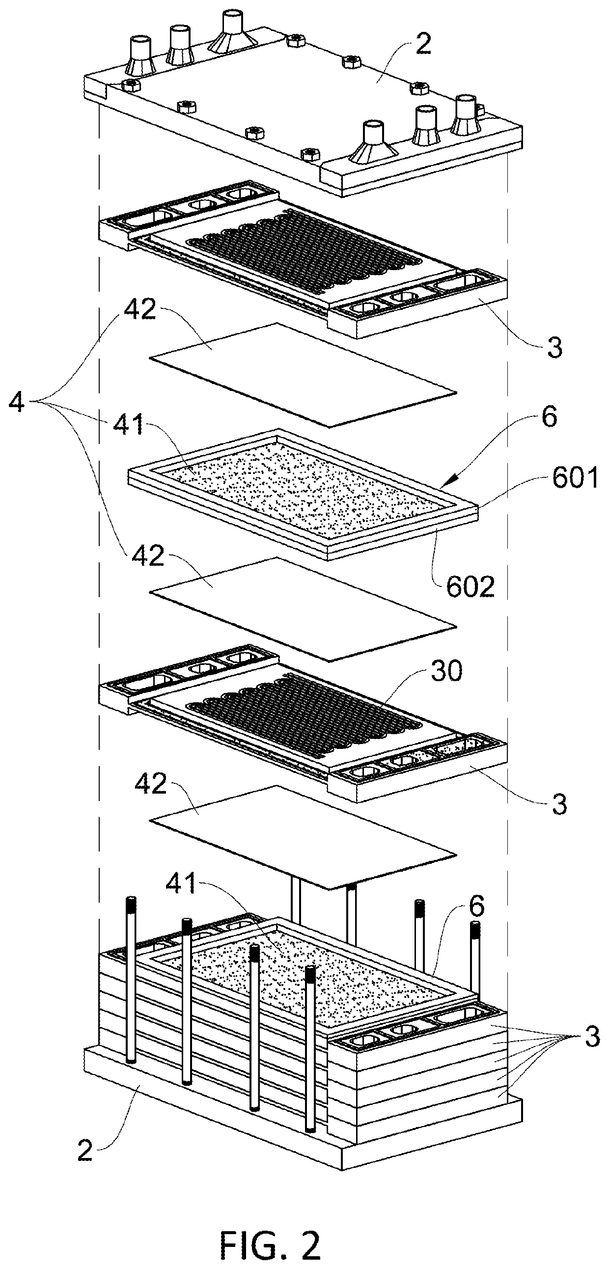
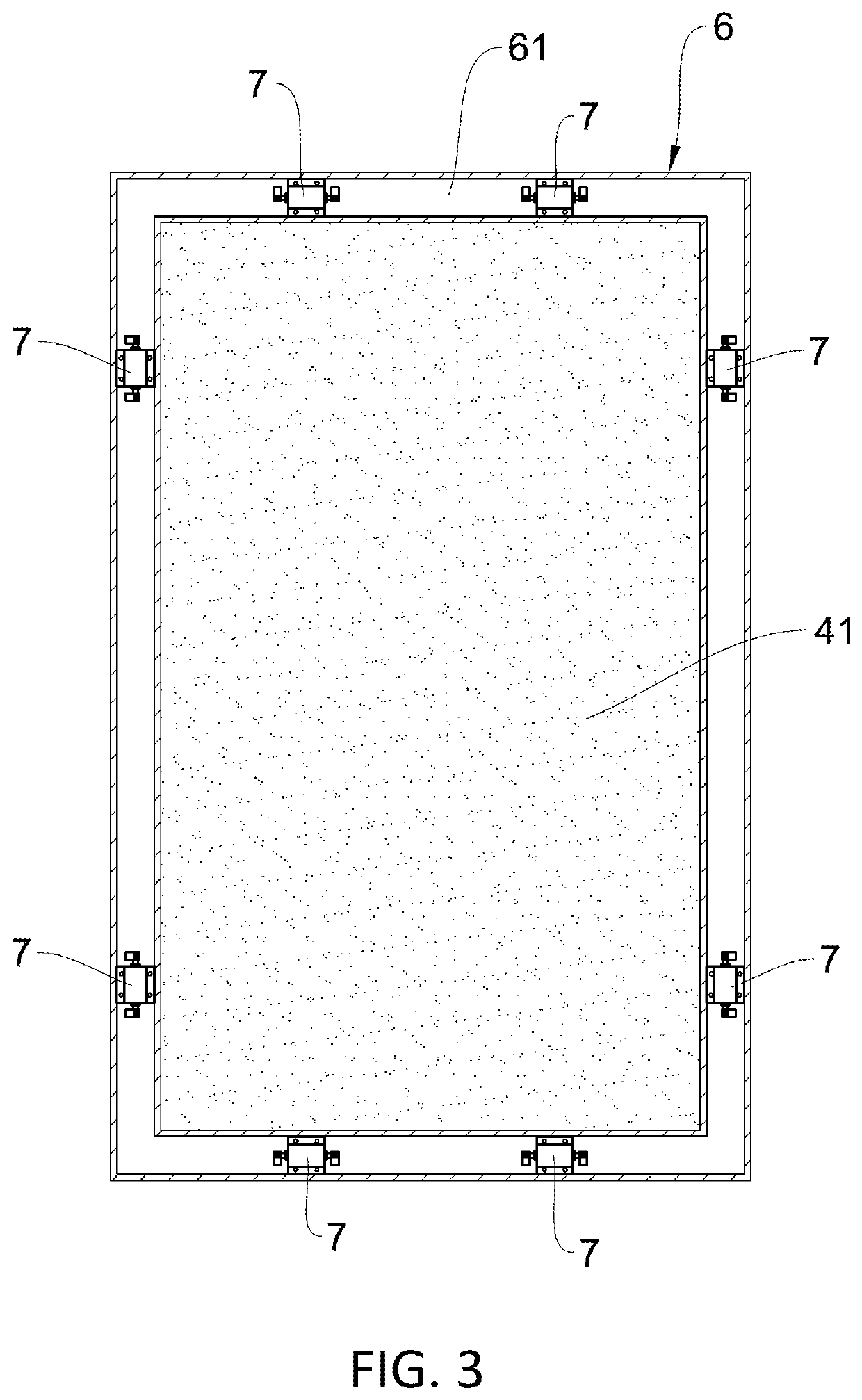
[0019]As illustrated in FIG. 1 to FIG. 4, an anti-passivation, anti-blockage and efficiency-enhancing ultrasonic fuel cell, comprises a front end plate 1, a rear end plate 2, a plurality of electrode plates 3 arranged between the front end plate 1 and the rear end plate 2, a reaction membrane 4 clamped between every two adjacent electrode plates 3, and screw nut assemblies 5 fixing the front end plate 1, the electrode plates 3 and the rear end plate 2 together to form a galvanic pile. The present invention also comprises membrane frames 6 and ultrasonic elements 7. Each reaction membrane 4 is clamped in a respective membrane frame 6, and the ultrasonic elements 7 are arranged in each membrane frame 6. A concave ring slot 31 is provided on each of two sides of each electrode plate 3 to embed a respective membrane frame 6 on each side. The reaction membrane 4 is clamped between every two adjacent electrode plates 3 by being embedded in a respective concave ring slot 31 via a respectiv...


PUM


Abstract

An anti-passivation, anti-blockage and efficiency-enhancing ultrasonic fuel cell, which includes a front end plate, a rear end plate, electrode plates arranged between the front end plate and the rear end plate, a reaction membrane clamped between every two adjacent electrode plates, and screw nut assemblies fixing the front end plate, the electrode plates and the rear end plate together to form a galvanic pile; a reaction membrane is clamped in each membrane frame, and ultrasonic elements are arranged in the membrane frame. A concave ring slot is provided on each of two sides of each electrode plate to embed the membrane frame. The reaction membrane is clamped between every two adjacent electrode plates by being embedded in a respective concave ring slot via a respective membrane frame.

Description

BACKGROUND OF THE INVENTION[0001]The present invention relates to fuel cell products and more particularly pertains to an ultrasonic fuel cell.[0002]Fuel cell, also known as electrochemical generator, is a chemical device which converts chemical energy in fuels to electrical energy. Like hydro power, thermos power and nuclear power, fuel cell is one of the modern technologies for electricity generation. It is highly efficient as it converts the Gibbs free energy in the chemical energy of the fuel into electrical energy via electrochemical reaction without being limited by the Carnot cycle. Fuel cell uses fuel and oxygen as the basic components which minimize, if not eliminate, the emission of harmful gases. The absence of motor transmission parts also prevents noise production. Therefore, from the perspectives of energy conservation and environmental protection, fuel cell is considered to be an electricity generation technology with a promising development prospect.[0003]Fuel cell i...

Claims


Application Information

Patent Timeline
IPC IPC(8): H01M8/0662H01M8/04082H01M8/0273H01M8/0276H01M8/0258B08B7/02B08B9/027
CPCH01M8/0662H01M8/04201H01M8/0273H01M2008/1095H01M8/0258B08B7/028B08B9/027H01M8/0276H01M8/04701H01M8/04302H01M8/04253H01M8/04225H01M8/04268Y02E60/50Y02P70/50
Inventor PENG, ZHIJUN
Owner PENG ZHIJUN
Why Eureka
Eureka Blog
Learn More