Method to reduce noise in microphone circuits

a microphone circuit and noise reduction technology, applied in the field of computing devices, can solve the problems of increasing power supply noise, high power consumption of high-performance graphics cards, and insufficient noise reduction solutions, and achieve the effect of removing common mode nois

Pending Publication Date: 2022-08-25
CREATIVE TECH CORP
View PDF0 Cites 0 Cited by
  • Summary
  • Abstract
  • Description
  • Claims
  • Application Information

AI Technical Summary

Benefits of technology

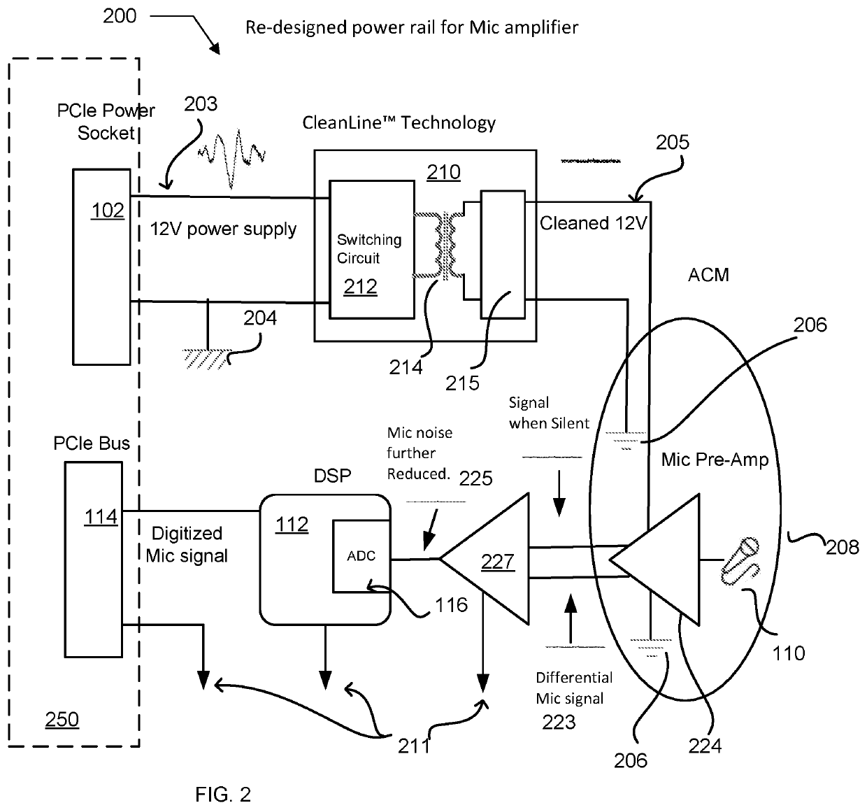
[0007]In yet another embodiment the audio processing system further includes a differential amplifier connected between the microphone preamp and the digital signal processor block. The differential amplifier is configured to remove common mode noise from the microphone preamp output signal.

Problems solved by technology

To meet this increased demand for power, computer manufacturers have provided external power connectors due at least in part to the insufficient power available from motherboard busses, such as the PCI / e busses.
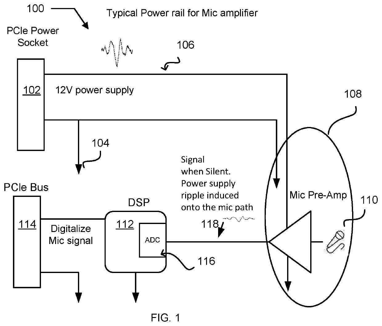
Unfortunately, the higher power consumption of these high performance graphics cards also comes with increased power supply noise.
But given the high gains used in the microphone amplifiers for voice communications, these solutions are often insufficient to reduce the noise to a level acceptable for a high-end product.

Method used


Image

  • Method to reduce noise in microphone circuits
  • Method to reduce noise in microphone circuits
  • Method to reduce noise in microphone circuits

Examples


Embodiment Construction

[0014]Reference will now be made in detail to preferred embodiments of the invention. Examples of the preferred embodiments are illustrated in the accompanying drawings. While the invention will be described in conjunction with these preferred embodiments, it will be understood that it is not intended to limit the invention to such preferred embodiments. On the contrary, it is intended to cover alternatives, modifications, and equivalents as may be included within the spirit and scope of the invention as defined by the appended claims. In the following description, numerous specific details are set forth in order to provide a thorough understanding of the present invention. The present invention may be practiced without some or all of these specific details. In other instances, well known mechanisms have not been described in detail in order not to unnecessarily obscure the present invention.

[0015]It should be noted herein that throughout the various drawings like numerals refer to ...


PUM


Abstract

A computer sound card includes a power supply noise isolation circuit for reducing ground plane noise generated during application of heavy electrical loads to the power supply, such as loads presented by computer GPUs. The power supply isolation circuit isolates the output ground from the ground presented from the power supply to the isolation circuit input. The isolation circuit in one embodiment includes switching circuitry and a transformer to reduce the power supply ripple noise that might otherwise be introduced by the power supply into an amplifier such as a microphone preamp. In some embodiments a differential amplifier stage is added to the output of the microphone preamp stage to further reduce noise, such as common mode noise.

Description

CROSS REFERENCES TO RELATED APPLICATIONS[0001]This application is a National Stage (§ 371) of International Application No. PCT / SG2020 / 050388 (Attorney Docket Number CTLP530 WO), filed 7 Jul. 2020 and entitled “METHOD TO REDUCE NOISE IN MICROPHONE CIRCUITS”, which claims the benefit of U.S. Provisional Application No. 62 / 871,654 (Attorney Docket Number CTLP530PRV), filed 8 Jul. 2019 and entitled “METHOD TO REDUCE NOISE IN MICROPHONE CIRCUITS”, the disclosure of which is herein incorporated by reference in its entirety.BACKGROUND OF THE INVENTION1. Field of the Invention[0002]The present invention relates to computing devices with input / output circuitry. More particularly, the present invention relates to power supply noise control in audio processing circuitry such as sound cards for computing devices.2. Description of the Related Art[0003]Over time the importance of graphics cards and chips with respect to computing devices has increased. To meet these increased demands, graphics c...

Claims


Application Information

Patent Timeline
Patent Type & Authority Applications(United States)
IPC IPC(8): H03F1/26H03F3/183H04R3/00
CPCH03F1/26H03F3/183H04R3/00H04R2410/03H03F2200/459H03F2200/372H03F2200/03H03F3/181H02M1/12H03F2200/189H02M3/33507H02M1/15H04R2410/00G06F3/162H02M1/123
Inventor LIAN, YAM FEILOKE, SIEW LING
Owner CREATIVE TECH CORP
Why Eureka
Try Eureka