Thermal insulation structure in side section in which two-side supporting frame window sash overlaps door frame in sliding window system

Pending Publication Date: 2022-09-08
FILOBE
View PDF0 Cites 0 Cited by
  • Summary
  • Abstract
  • Description
  • Claims
  • Application Information

AI Technical Summary

Benefits of technology

This patent describes a sliding window system that improves energy efficiency and prevents condensation. It does this by using a foamed insert member that blocks thermal bridges and minimizes heat transfer between the window frame and the chassis. Additionally, the system uses an aluminum side cap, which provides stability against wind pressure and ensures good thermal insulation performance. Overall, the system ensures maximum energy efficiency and provides improved window performance.

Problems solved by technology

Furthermore, despite the high indoor temperature, the side cap 2b1 of the window chassis 2b made of an aluminum (AL) material has a low surface temperature, thereby exhibiting a problem in that dew condensation occurs.
Nevertheless, it also cannot prevent heat loss due to convection of air present in the insertion pocket 1v, as well as the synthetic resin or carbon fiber side cap 2b1 alone, in an environment where strong wind acts on the glass, it is difficult to properly control the excessive deformation occurring in the glass support insulation bracket 2gb, there is a problem of exposing structural weaknesses.

Method used


Image

  • Thermal insulation structure in side section in which two-side supporting frame window sash overlaps door frame in sliding window system
  • Thermal insulation structure in side section in which two-side supporting frame window sash overlaps door frame in sliding window system
  • Thermal insulation structure in side section in which two-side supporting frame window sash overlaps door frame in sliding window system

Examples


first embodiment

[0033]In addition, as shown enlarged as [Part-C1] in FIG. 6d, the foamed insert member for blocking thermal bridge 150 according to the present invention is made of a composite material. That is, an assembly of the composite material provided by attaching foam rubber 156 or foamed Styrofoam™ (foamed styrene resin, expanded polystyrene), which has excellent thermal insulation properties but relatively low ability to maintain shape and durability, to a thin synthetic resin plate 152 having relatively low thermal insulation performance but high ability to maintain shape and durability (as illustrated in FIG. 6d) is installed in the insertion pocket 100v of the door frame 100 in the shape of the ‘⊂’ shape (the channel shape with one inner side open) and on an outer surface of the insertion pocket 100v of the thin synthetic resin plate 152, that is, toward an inner side 110 of the door frame 100, as a square-shaped foam material, foam rubber 156, or foamed Styrofoam™ (foamed styrene resi...

second embodiment

[0034]On the other hand, according to the present invention additionally shown in FIG. 7, the foamed insert member for blocking thermal bridge 150 may be formed by integrally molding a foamed plastic-based heat insulating material 158 that can have both appropriate heat insulation properties and shape retention properties (ability to maintain shape).

[0035]Preferably, fitting protrusions 110a and 152a or fitting grooves for mutual fitting coupling are provided between the foamed insert member for blocking thermal bridge 150 and the inner side 110 of the door frame 100.

[0036]And, the foam rubber 156 (foam rubber) insulator having a closed-cell structure enlarged as [Part-C1] in FIG. 6d has excellent moisture-proofing properties, so even time elapses after construction, thermal conductivity maintains lower than that of other insulators and relatively stable status, therefore it has the advantage of long-lasting insulation retention.

[0037]In addition, the foamed plastic-based heat insul...


PUM


Abstract

The present invention relates to a thermal insulation structure of a door frame in which a moving window (sliding window) constituting a sliding window system is installed, and more particularly, a two-side supporting frame window supporting both sides of a glass window constituting a sliding window system, more particularly, relates to an insulating structure in a side section of a door frame into which the side portion of the sliding window that is moved when closing the sliding window of the supporting frame window type is pocketed, that is, the insulating structure of the side section of the door frame.

Description

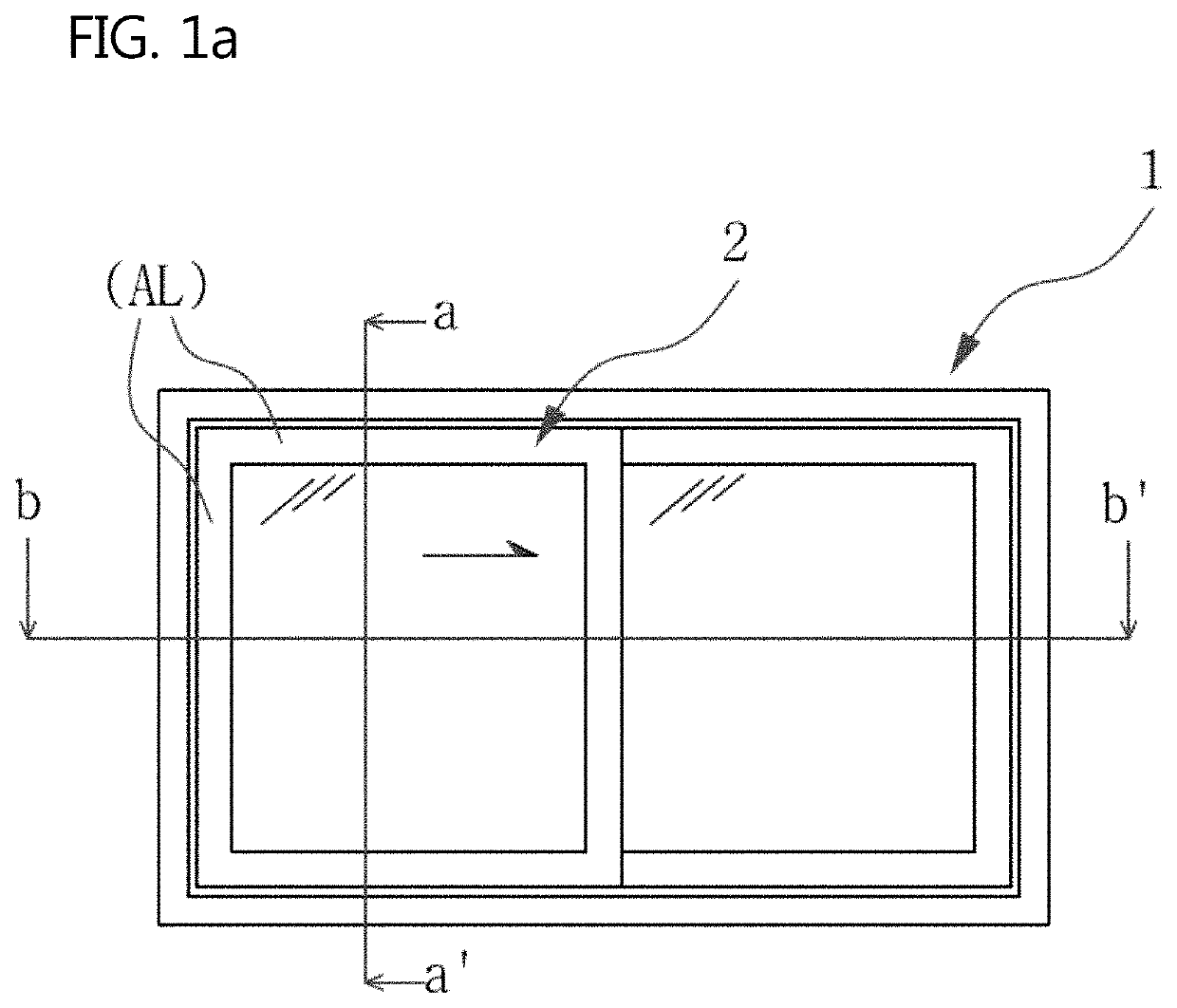
TECHNICAL FIELD[0001]The present invention relates to a heat insulation (thermal insulation) structure of a door frame in which a moving window (sliding window) constituting a sliding window system is installed. More specifically, it relates to a heat insulation structure in the side section of a door frame into which the side of a sliding window is moved and inserted in a pocket type when closing the sliding window of a two-side supporting frame window type supporting both sides of the glass window constituting the sliding window.BACKGROUND ART[0002]In general, when a sliding window (moving window) and a fixed window of four-side supporting frame window type that support the four sides of the glass window with thick supporting frames as a movable window (sliding window) and a fixed window constituting a sliding window system are used (FIG. 1a), as shown in a-a′ cross-sectional view (longitudinal cross-sectional view) of FIG. 1b, the sliding window system has a structure in which a ...

Claims


Application Information

Patent Timeline
IPC IPC(8): E06B3/263E06B3/26E06B3/273
CPCE06B3/26347E06B3/26E06B3/2735E06B2003/26378E06B3/46E06B3/263E06B3/267E06B3/4618
InventorLEE, KWANG-SEOG
OwnerFILOBE