Filtration apparatus and filter washing method therefor

a technology of filtration apparatus and filter washing method, which is applied in the direction of separation process, filtration separation, transportation and packaging, etc., can solve the problems of difficult to reduce manufacturing costs, limit the diameter the backwashing mechanism is not easily removed during maintenance so as to improve the strength of the filter element, improve the maintainability, and reduce the dimension of the filtration apparatus

Pending Publication Date: 2022-09-15
FUJI FILTER MFG
View PDF0 Cites 0 Cited by
  • Summary
  • Abstract
  • Description
  • Claims
  • Application Information

AI Technical Summary

Benefits of technology

[0011]According to the filtration apparatus of the present invention, it is possible to achieve reduction in dimension of the filtration apparatus, improvement in strength of a filter element, and improvement of maintainability.

Problems solved by technology

However, since a backwashing mechanism for performing backwashing and a high-pressure washing mechanism for performing high-pressure washing are arranged outside the cylindrical filter element, there is a limit to reducing a diameter of the filtration apparatus, and it is difficult to reduce manufacturing costs.
Furthermore, since the filtration is performed in the direction from the outer circumferential surface toward the inner circumferential surface of the cylindrical filter element, an inward crushing force acts on the filter element by a target fluid, which is not preferable for maintaining the strength of the filter element.
Furthermore, since a pipe for discharging a backwashing fluid generated by the backwashing mechanism protrudes to the outside of the filtration apparatus in a direction different from a removal direction of the backwashing mechanism, the backwashing mechanism is not easily removed during maintenance of the filtration apparatus.

Method used


Image

  • Filtration apparatus and filter washing method therefor
  • Filtration apparatus and filter washing method therefor
  • Filtration apparatus and filter washing method therefor

Examples


first embodiment

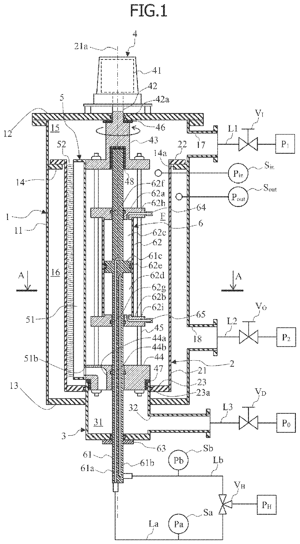
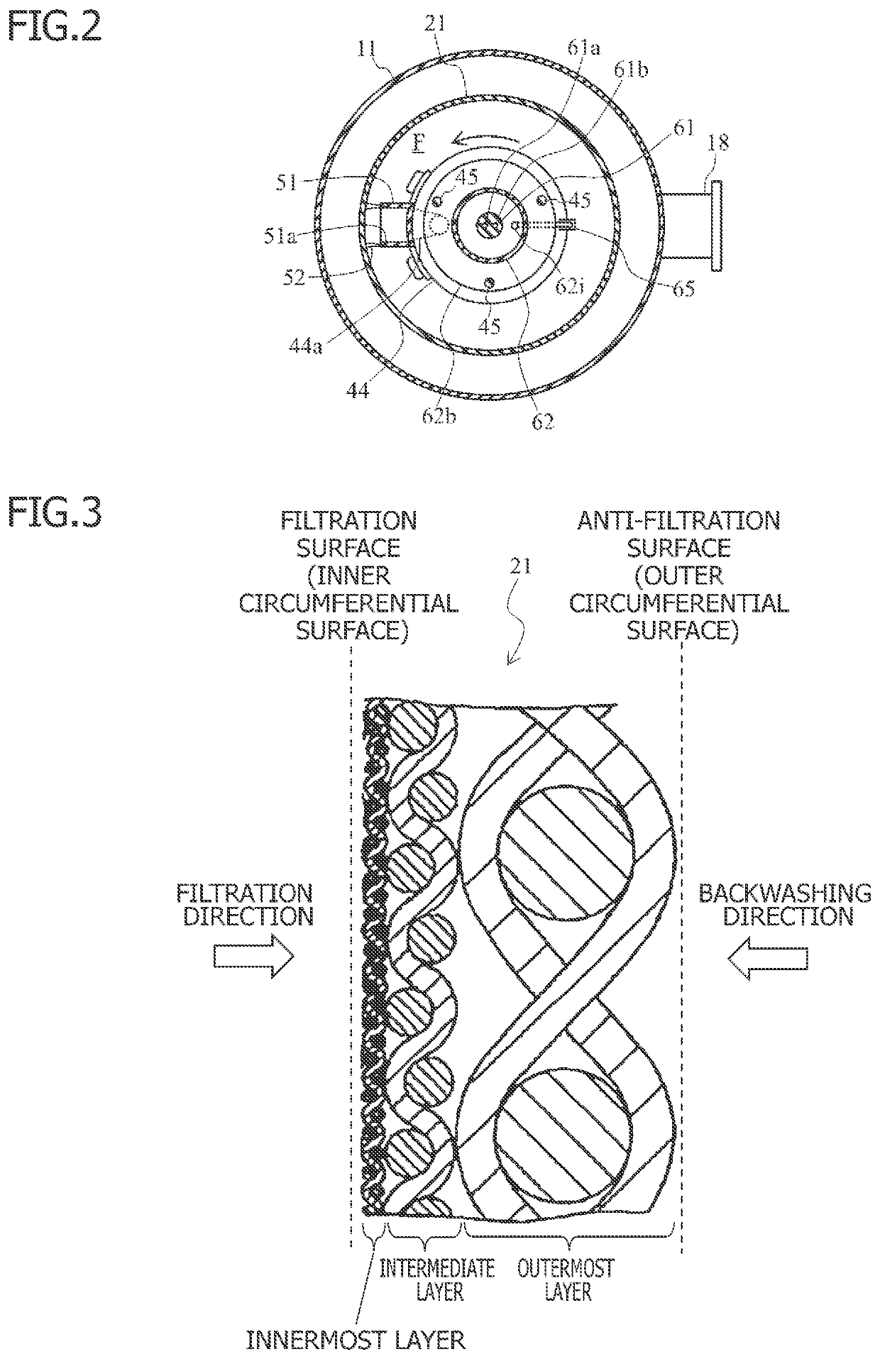
[0032]FIGS. 1 and 2 show an example of a filtration apparatus according to a first embodiment. The filtration apparatus has a filtering function of making various fluids to be filtered (hereinafter, referred to as “target fluids”) pass through a built-in filter element to perform filtration. Examples of the target fluids include river water, lake water, or seawater, liquid used in general industry such as cooling water or process liquid for various apparatuses, oil such as lubricating oil or diesel fuel oil, various raw material gases used in chemical factories, or ship ballast water. Specifically, the filtration apparatus includes a casing 1 and a filter unit 2 as a configuration that embodies the filtering function.

[0033]The casing 1 is a tubular body (for example, a cylindrical body) 11 forming an outer shell of the filtration apparatus, and has a closed space therein with a first casing lid plate 12 that closes one end opening and a second casing lid plate 13 that closes the oth...

second embodiment

[0085]FIGS. 11 and 12 shows an example of a filtration apparatus according to a second embodiment. In the present embodiment, differences from the first embodiment will be mainly described, and components similar to those of the filtration apparatus according to the first embodiment are denoted with the same reference numerals and description will be omitted for simplicity. The same applies to the following other embodiments.

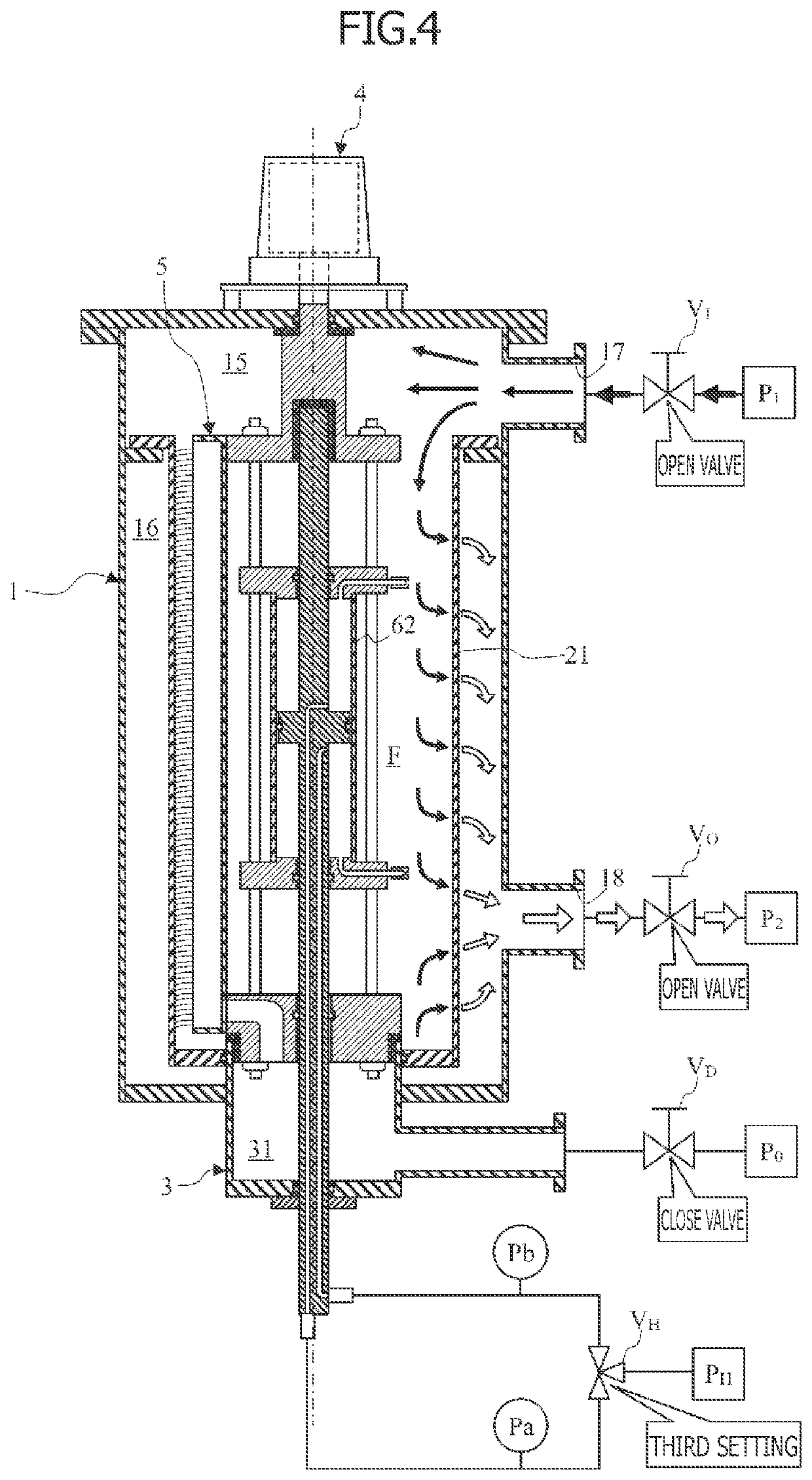
[0086]As described in the first embodiment, when the backwashing is performed prior to the high-pressure washing, almost all fine particulate trapped materials trapped from the filtration surface side of the filter element 21 are removed together with the backwashing fluid. However, when the backwashing is insufficient, the fine particulate trapped materials may be peeled off by the high-pressure washing and remain in the internal space F of the filter element 21. Therefore, in consideration of the possibility that the trapped materials of the filter element 21 ...

third embodiment

[0094]FIG. 15 shows an example of a filtration apparatus according to a third embodiment. The filtration apparatus of the present embodiment is different from the filtration apparatus of the first embodiment in that the piston rod 61 is fixed to the first end rotating body 43 and the second end rotating body 44 so as not to be relatively rotatable and rotates integrally with the rotary drive mechanism 4. For this reason, the following components in the first embodiment are omitted in the present embodiment. That is, the intermediate bearing 48 for supporting the piston rod 61 so as to be rotatable relative to the first end rotating body 43 and the fixture 63 for fixing the piston rod 61 to the backwashing drain case 3 are omitted. Furthermore, since the piston rod 61 is closely fixed to the inner circumferential surface of the through hole of the second end rotating body 44, the sealing member 44b between the second end rotating body 44 and the piston rod 61 is omitted.

[0095]An annu...


PUM

PropertyMeasurementUnit
pressureaaaaaaaaaa
distanceaaaaaaaaaa
rotary speedaaaaaaaaaa

Abstract

A filtration apparatus includes: a cylindrical filter element formed in a cylindrical shape to filter a target fluid guided through an one end opening of the filter element in such a manner that the target fluid passes in a direction from an inside toward an outside of the filter element; a backwashing mechanism drawing the filtered fluid in a direction from the outside toward the inside of the filter element; a high-pressure washing mechanism injecting a high-pressure fluid so as to pass through the filter element in the direction from the inside toward the outside of the filter element; and a rotary drive mechanism rotating the backwashing mechanism and the high-pressure washing mechanism around an axial line of the filter element in an internal space of the filter element.

Description

CROSS-REFERENCE TO RELATED APPLICATION[0001]The present application is a national phase entry under 35 U.S.C. § 371 of International Application No. PCT / JP2020 / 023358, filed Jun. 15, 2020, which claims priority from Japanese Patent Application No. 2019-141543, filed Jul. 31, 2019, all of which are incorporated herein by reference.TECHNICAL FIELD[0002]The present invention relates to a filtration apparatus that filters a fluid using a filter element and a filter washing method for the filtration apparatus.BACKGROUND ART[0003]An example of a filtration apparatus and a filter washing method for the filtration apparatus is disclosed in Patent Document 1 in which filtration is performed in a direction from an outer circumferential surface toward an inner circumferential surface of a cylindrical filter element and backwashing and high-pressure washing from the outer circumferential surface are performed in a state in which the filter element is rotated.REFERENCE DOCUMENT LISTPatent Docume...

Claims


Application Information

Patent Timeline
Patent Type & Authority Applications(United States)
IPC IPC(8): B01D29/64B01D29/23B01D29/66B01D29/68
CPCB01D29/6484B01D29/23B01D29/6446B01D29/668B01D29/682B01D29/688B01D29/11B01D29/68B01D29/66B01D29/606B01D35/30B01D29/6492B01D46/2403B01D46/682B01D46/72B01D24/48B01D29/60B01D29/6438
Inventor TAKAHASHI, YUICHI
Owner FUJI FILTER MFG
Why Eureka
Try Eureka