
Cutting apparatus

a cutting device and cutting blade technology, applied in the field of cutting tools, can solve the problems of reducing corroding and wear of the cutting blade due to the cutting liquid, and easy corrosion so as to reduce the strength of the cutting blade, reduce the damage to the cutting blade, and improve the cutting

Pending Publication Date: 2022-09-29
DISCO CORP
View PDF0 Cites 0 Cited by
  • Summary
  • Abstract
  • Description
  • Claims
  • Application Information

AI Technical Summary

Benefits of technology

The present invention provides a cutting apparatus that can prevent the corrosion of the cutting blade caused by the cutting liquid. This is achieved by adding a corrosion layer made of a material that has a higher tendency to ionize than the binder of the cutting edge of the cutting blade. The corrosion layer sacrificially corrodes when supplied with the cutting liquid, which prevents the cutting blade from getting corrosion damage and maintains its strength. This reduces the likelihood of processing defects and damage to the cutting blade.

Problems solved by technology

When the workpiece is cut by using the cutting apparatus, and the supply of the cutting liquid to the cutting blade is continued, the cutting blade corrodes and wears due to the cutting liquid.
In particular, when pure water mixed with carbon dioxide (carbonated water) is used as the cutting liquid, the corrosion of the cutting blade progresses easily.
As a result, the strength of the cutting blade is decreased, and damage to the cutting blade and a processing defect in the workpiece tend to occur.

Method used


Image

  • Cutting apparatus
  • Cutting apparatus
  • Cutting apparatus

Examples


Embodiment Construction

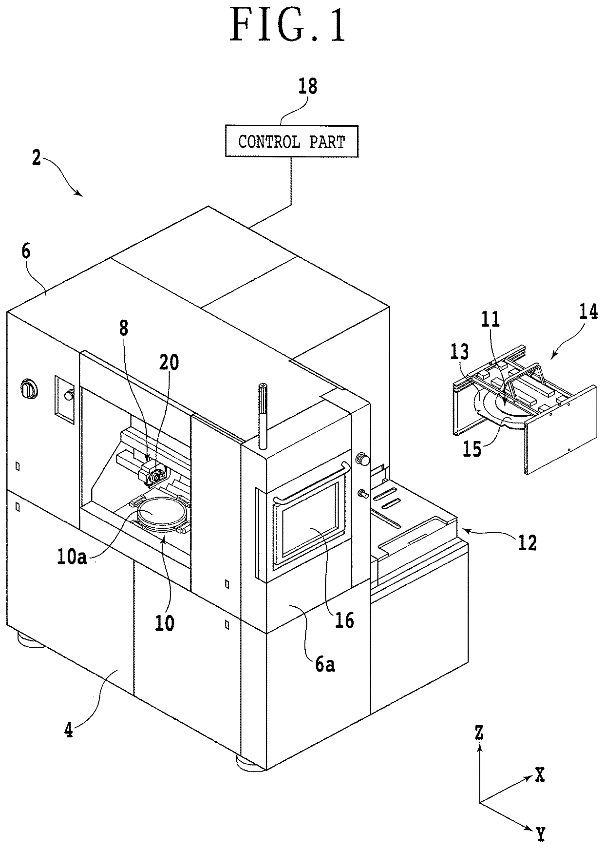
[0017]The present embodiment will hereinafter be described with reference to the accompanying drawings. An example of a configuration of a cutting apparatus according to the present embodiment will first be described. FIG. 1 is a perspective view depicting a cutting apparatus 2. Incidentally, in FIG. 1, an X-axis direction (a processing feed direction, a left-right direction, or a first horizontal direction) and a Y-axis direction (an indexing feed direction, a forward-rearward direction, or a second horizontal direction) are directions perpendicular to each other. In addition, a Z-axis direction (a vertical direction, an upward-downward direction, or a height direction) is a direction perpendicular to the X-axis direction and the Y-axis direction.

[0018]The cutting apparatus 2 includes a base 4 that supports and houses each constituent element constituting the cutting apparatus 2. A cover 6 that covers an upper surface side of the base 4 is provided to the upper side of the base 4. ...


PUM


Abstract

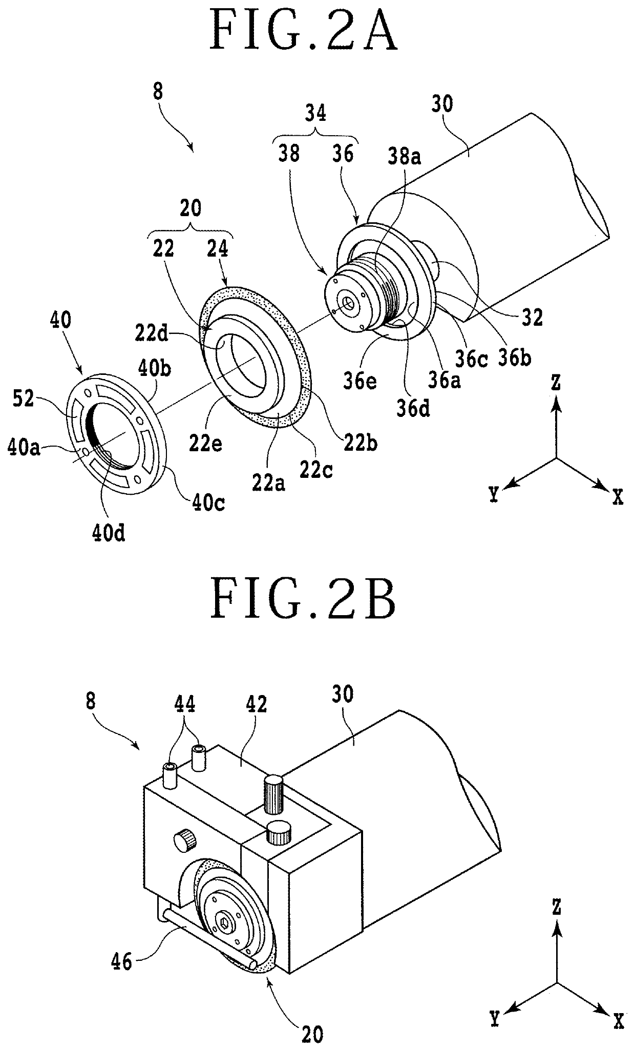
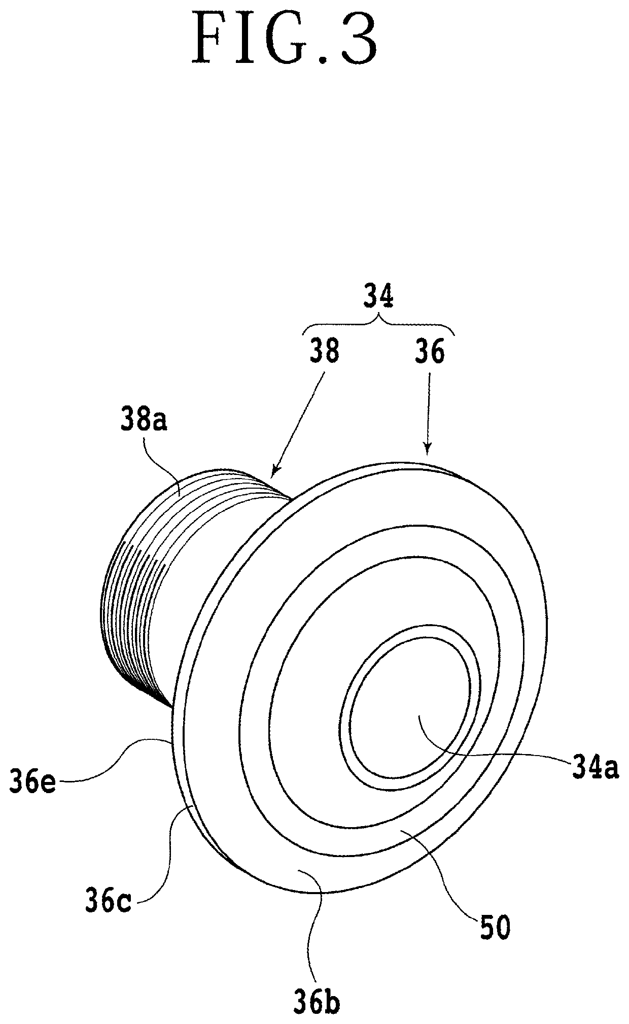
A cutting apparatus includes a chuck table configured to hold the workpiece, and a cutting unit fitted with a cutting blade including an annular base and a cutting edge that includes abrasive grains and a binder configured to fix the abrasive grains, and is formed along an outer circumferential edge of the base. The cutting unit includes a spindle, a blade mount fitted to a distal end portion of the spindle, and a fixing nut configured to fix the cutting blade to the blade mount, and the blade mount or the fixing nut is provided with a corrosion layer formed of a material having a higher ionization tendency than a material constituting the binder.

Description

BACKGROUND OF THE INVENTIONField of the Invention[0001]The present invention relates to a cutting apparatus that cuts a workpiece.Description of the Related Art[0002]A device chip manufacturing process uses a wafer having a device formed in each of a plurality of regions demarcated by a plurality of streets (planned dividing lines) arranged in a lattice manner. A plurality of device chips including respective devices are obtained by dividing the wafer along the streets. The device chips are incorporated into various electronic apparatuses such as mobile telephones, or personal computers.[0003]A cutting apparatus is used to divide the wafer. The cutting apparatus includes a chuck table that holds a workpiece, and a cutting unit that performs cutting processing on the workpiece. The cutting unit includes a spindle. A distal end portion of the spindle is fitted with an annular cutting blade that cuts the workpiece (see Japanese Patent Laid-Open No. 2000-87282). The wafer is cut and div...

Claims


Application Information

Patent Timeline
Patent Type & Authority Applications(United States)
IPC IPC(8): B24B27/06B24B41/06
CPCB24B27/06B24B41/06B24B27/0683B24B41/068B24B41/04B24B45/003B24B57/02H01L21/78H01L21/67092B24B27/0616B28D5/022
Inventor AIKAWA, HIROKI
Owner DISCO CORP
Learn More