Flame monitoring in a flash point determination or combustion point determination

a technology of flash point and detection point, which is applied in the direction of material flash point, measurement device, instruments, etc., can solve the problems of affecting the quality of the sample, the risk of a fire, and the possibility of so-called “burning”

Pending Publication Date: 2022-11-03
ANTON PAAR PROVETEC
View PDF0 Cites 2 Cited by
  • Summary
  • Abstract
  • Description
  • Claims
  • Application Information

AI Technical Summary

Problems solved by technology

In a flash point determination and / or combustion point determination, there is the risk of a fire of the sample.
For example, the sample may be inflamed (by itself or by an igniter) and may permanently burn under flame formation.
Moreover, a so-called “burn” may occur, i.e. a short-term strong unintended inflammation, when the vapor forms so fast, that in case of an ignition, a flame is generated for a short term outside or also inside the sample chamber.
However, temperature sensors for flame monitoring and / or fire monitoring and burn monitoring have disadvantages with respect to a responding behavior, a response time, an aging, and a mechanical vulnerability.
When the position of the measuring device is selected adversely and the measurement is performed under radiation of light with a high UV-portion, the reliability may be impaired.
Additionally, using certain UV-light filtering materials (e.g. window glass) prevents a reliable detection.
Since not each combustion generates the same amount of UV-light, the detection of some samples may lead to problems.Using temperature sensors may be suboptimal due to multiple factors: i) varying / high environmental heat may lead to disturbances, ii) response velocity and sensitivity is impaired by the kind of installation: material specific coefficients of thermal conductivity and thermal conductivity resistances delimit the time of reaction, iii) a need of using multiple sensors, to cover the necessary detection area, and iv) error signals may be generated by adjacent hot parts of the measuring device (ignition approximately 1300° C., crucible lid and / or sample temperature up to 405° C.).

Method used


Image

  • Flame monitoring in a flash point determination or combustion point determination
  • Flame monitoring in a flash point determination or combustion point determination
  • Flame monitoring in a flash point determination or combustion point determination

Examples


Embodiment Construction

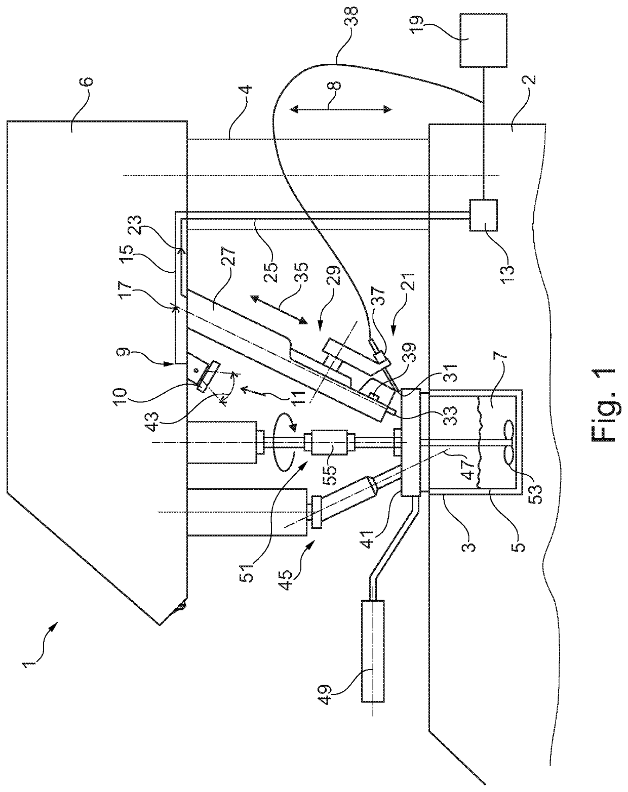
[0063]FIG. 1 illustrates in a schematic illustration a device for a flash point determination and / or combustion point determination and for flame monitoring, according to an embodiment of the present invention;

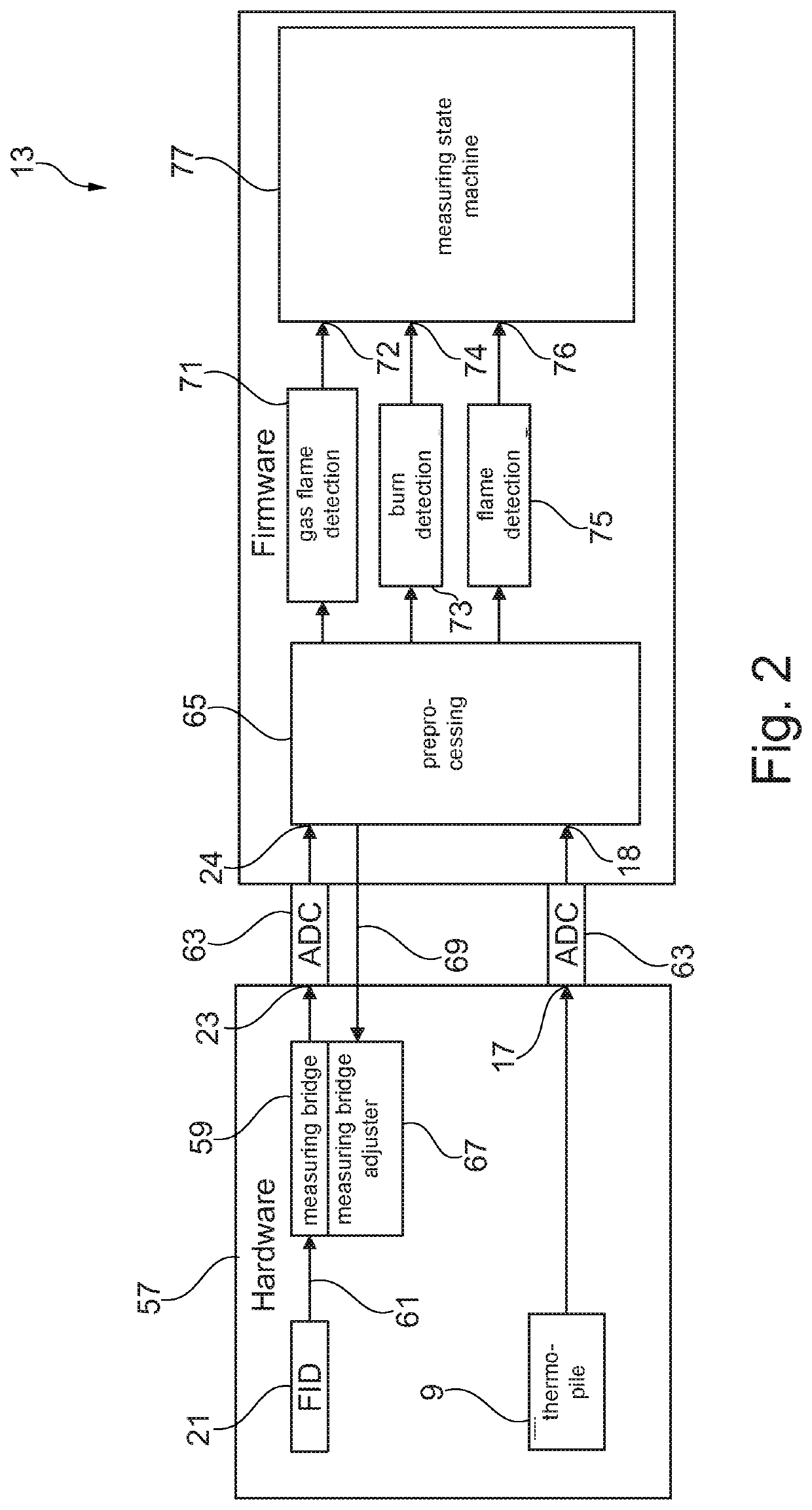
[0064]FIG. 2 schematically illustrates an evaluation system of a device for a flash point determination and / or combustion point determination and for a flame monitoring, according to an embodiment of the present invention; and

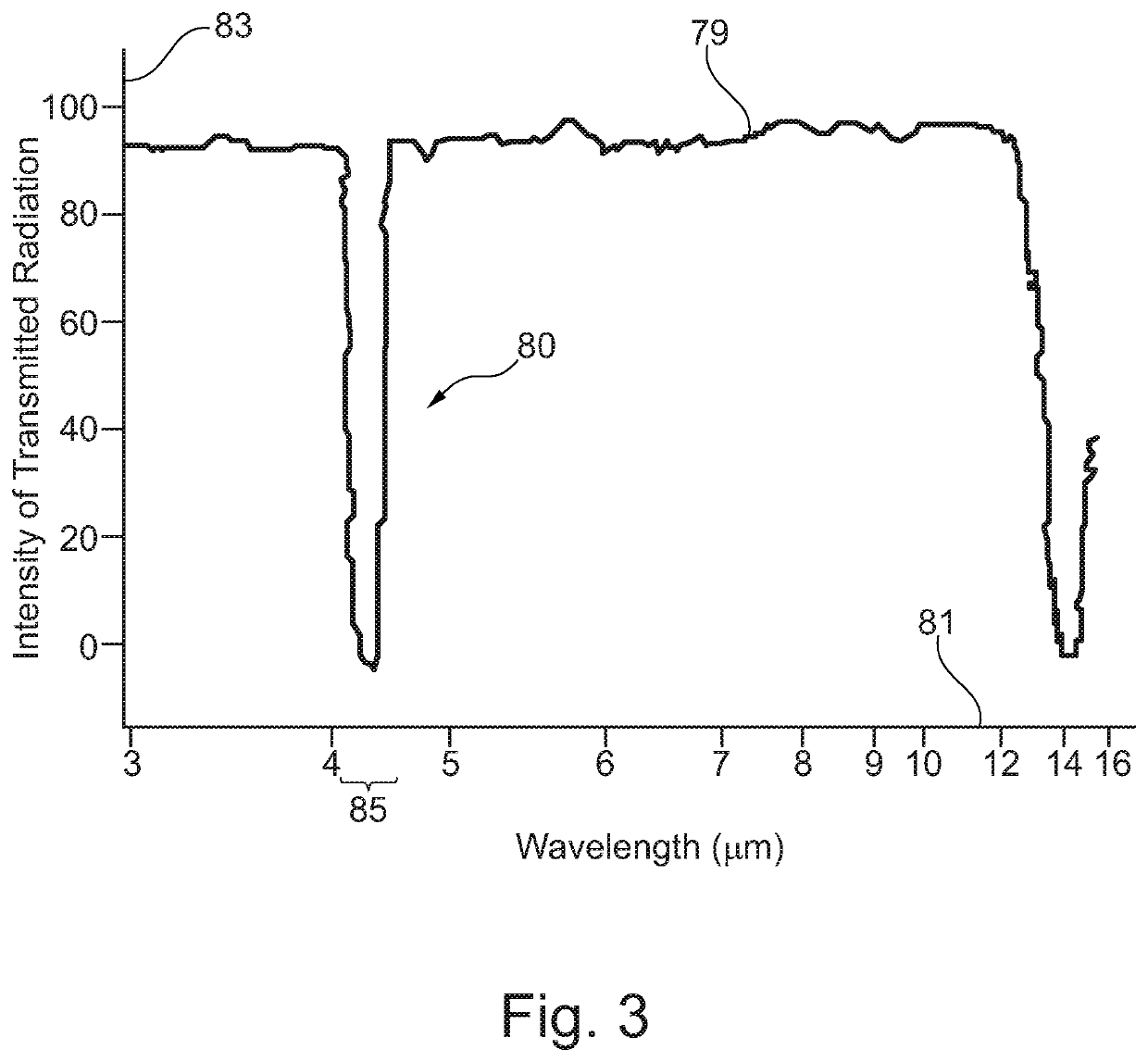
[0065]FIG. 3 illustrates a transmission spectrum of carbon dioxide as it is considered by embodiments of the present invention.

[0066]The device 1 for a flash point determination and / or combustion point determination of a liquid sample which is receivable in a container and for flame monitoring according to an embodiment of the present invention, which is schematically illustrated in a side sectional view in FIG. 1, encompasses a container reception 3 for receiving a container 5. In the container 5, a liquid 7 is received. By the device 1, the flash point ...


PUM

PropertyMeasurementUnit
wavelength rangeaaaaaaaaaa
electric potentialaaaaaaaaaa

Abstract

A device for a flash point: determination and/or combustion point determination of a liquid sample which is receivable in a container and for a flame detection is described, comprising: a container reception for receiving the container; an infrared sensor which is arranged to detect light which is generated by a flame in a region around or within the container; an evaluation system which is coupled with the infrared sensor and is configured to evaluate infrared sensor data of the infrared sensor, to indicate a fire or a burn based on the evaluation.

Description

CROSS-REFERENCE TO RELATED APPLICATIONS[0001]This application is a national US phase of PCT / EP2020 / 066725 which claims the benefit of the filing date of the German Patent Application No. 10 2019 120 512.3 filed 30 Jul. 2019, the disclosure of which is hereby incorporated herein by reference,TECHNICAL FIELD[0002]Embodiments of the present invention relate to a device for a flash point determination and / or combustion point determination of a liquid sample which is receivable in a container and for a flame monitoring. Furthermore, embodiments of the present invention relate to a method for a flame monitoring in a flash point determination and / or combustion point determination of a liquid sample which is receivable in a container.TECHNOLOGICAL BACKGROUND[0003]Flash point examination apparatuses are conventionally used for a characterization of combustibles (e.g. diesel, gas, kerosene, fuel oil), solvents, lubrication oils, or chemicals. According to the definition, the flash point is th...

Claims


Application Information

Patent Timeline
Patent Type & Authority Applications(United States)
IPC IPC(8): G01N25/52G01N33/22
CPCG01N25/52G01N33/227G01N33/22
Inventor STRASSER, FLORIANTUAEV, XENIA
Owner ANTON PAAR PROVETEC
Why Eureka
Try Eureka