
Phase-shift control method for power module, three-phase power module, and power system

a power module and control method technology, applied in the field of power electronic technology, can solve the problems of increasing the difficulty in designing the system structure, not facilitating the integration of the system, and the number of cells gets bigger, so as to reduce the number of modules and controllers, and achieve high-efficiency output and power-sharing control within a wide range. the effect of reducing the number of controllers

Pending Publication Date: 2022-11-17
DELTA ELECTRONICS SHANGHAI CO LTD
View PDF3 Cites 0 Cited by
  • Summary
  • Abstract
  • Description
  • Claims
  • Application Information

AI Technical Summary

Benefits of technology

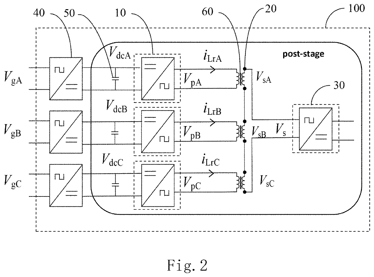
The invention provides a method for controlling the phase-shift of high-frequency modules, which helps to achieve high efficiency and power sharing. It also involves using a zero-sequence voltage to prevent fluctuations in the DC-Link voltage and to cancel out current imbalances in a three-phase resonant tank. The invention also introduces an isolated three-phase power module that reduces the number of modules and controllers needed.

Problems solved by technology

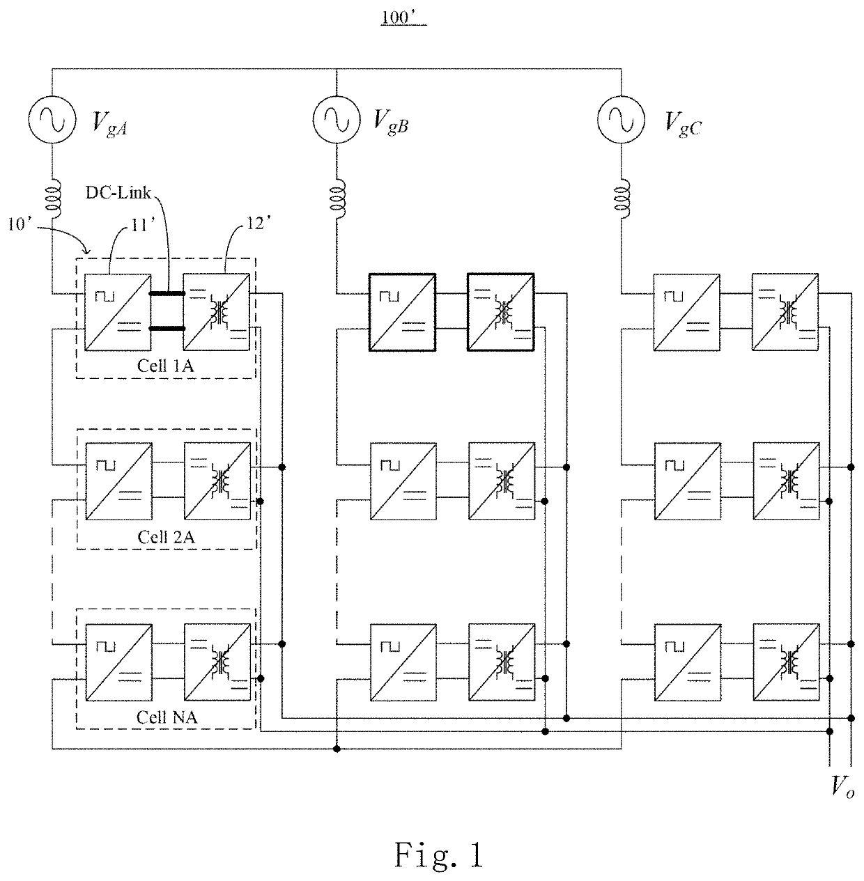
As can be seen from FIG. 1, the conventional topology includes 3*N cells, and the number of cells is numerous, which increases the difficulty in designing the structure of the system and does not facilitate the integration of the system.
When the system is further developed to high voltage, the number of cells gets bigger, i.e., increased by a multiple of 3, which does not facilitate further expansion.
Even if the LLC circuits use control loops for inhibiting fluctuation of the power, it is still difficult to inhibit double frequency fluctuation of currents in the LLC resonant cavity, causing additional loss of the LLC circuits.
Moreover, it is hard for the three-phase LLC circuits to share the currents, and the powers of the cells shall be balanced using a complex voltage-sharing current-sharing algorithm.
Meanwhile, the schemes of the LLC circuits for adjusting the output voltages are extremely limited.
Frequency modulation, phase shifting, or duty cycle regulation may be adopted, but frequency modulation affects the efficiency of the system, and phase shifting or duty cycle regulation results in the loss of Zero Voltage Switch (ZVS) of inverter circuits at the primary side of the LLC circuits, thereby increasing loss.
Similar to a voltage modulation method for the single-phase cells of the SST, the output of voltages within a wide range can be realized through phase-shift control between AC voltages at primary and secondary sides (voltage increasing) and control of a duty cycle at the primary side (voltage decreasing), but the case where ZVS is lost when outputting within a wide range also exists, which affects the efficiency of the system.
However, being a single-phase cell, it has two resonant cavities and two resonant circuits, resulting in a relatively high cost.

Method used


Image

  • Phase-shift control method for power module, three-phase power module, and power system
  • Phase-shift control method for power module, three-phase power module, and power system
  • Phase-shift control method for power module, three-phase power module, and power system

Examples


Embodiment Construction

[0035]The exemplary embodiments will now be described more fully with reference to the accompanying drawings. However, the exemplary embodiments can be implemented in various forms and shall not be understood as being limited to the embodiments set forth herein; on the contrary, these embodiments are provided so that this invention will be thorough and complete, and the conception of exemplary embodiments will be fully conveyed to those skilled in the art. In the drawings, the same reference sign denotes the same or similar structure, so their detailed description will be omitted.

[0036]When factors / components / the like described and / or illustrated here are introduced, the phrases “one”, “a(an)”, “the”, “said” and “at least one” refer to one or more factors / components / the like. The terms “include”, “comprise” and “have” refer to an open and included meaning and refer to additional factors / components / the like, in addition to the listed factors / components / the like. The embodiments may u...


PUM


Abstract

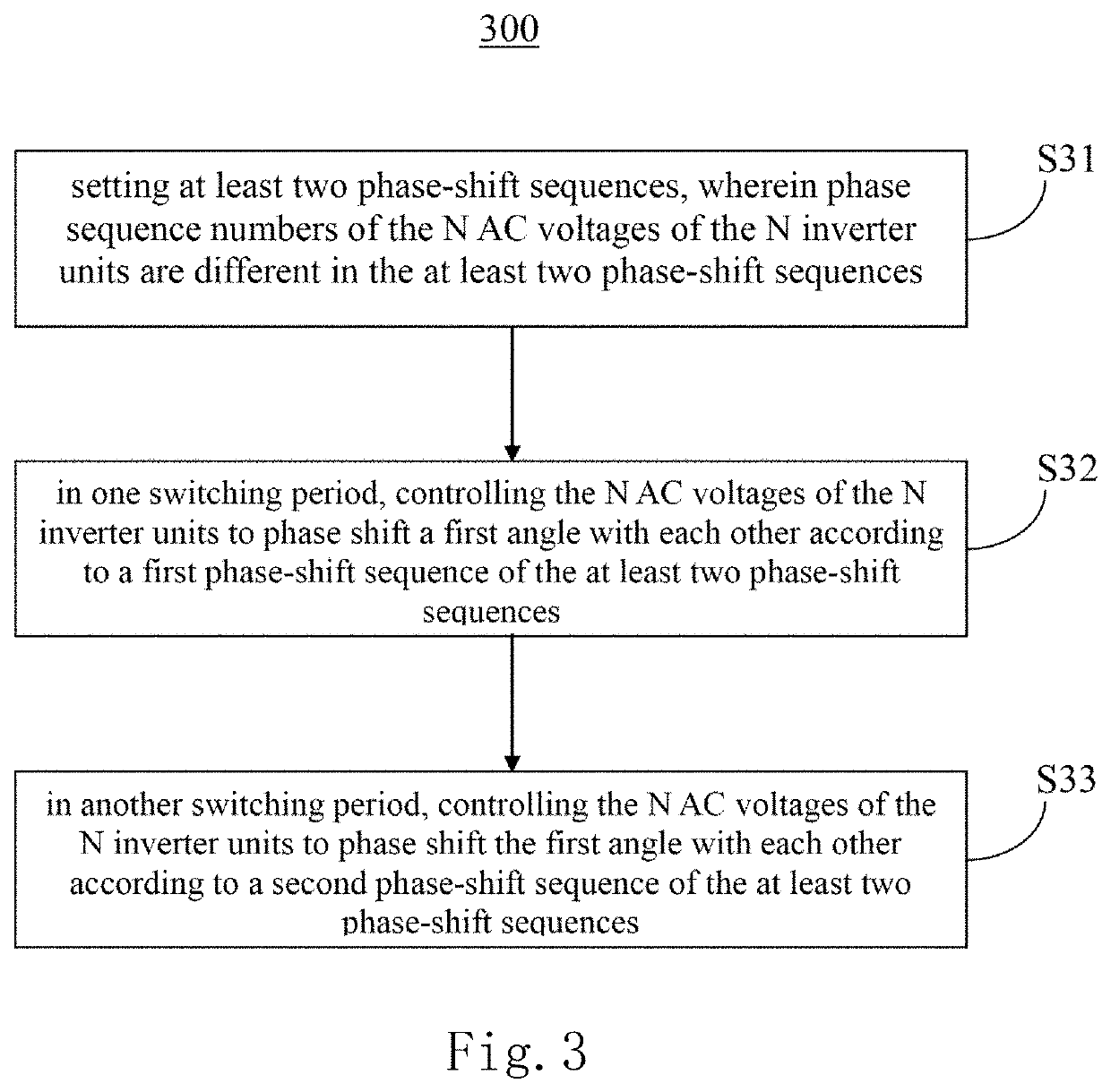
A power module includes N inverter units outputting N AC voltages and being coupled to N high-frequency AC terminals, wherein the N high-frequency AC terminals are cascaded and connected to a post-stage rectifier circuit. A phase-shift control method for the power module includes: setting at least two phase-shift sequences, wherein phase sequence numbers of the N AC voltages of the N inverter units are different in the at least two phase-shift sequences; in one switching period, controlling the N AC voltages of the N inverter units to shift a first angle according to a first phase-shift sequence of the at least two phase-shift sequences; and in another switching period, controlling the N AC voltages of the N inverter units to shift the first angle according to a second phase-shift sequence of the at least two phase-shift sequences.

Description

CROSS-REFERENCE TO RELATED APPLICATIONS[0001]This non-provisional application claims priority under 35 U.S.C. § 119(a) on Patent Application No. 202110529768.8 filed in P.R. China on May 14, 2021, the entire contents of which are hereby incorporated by reference.[0002]Some references, if any, which may include patents, patent applications and various publications, may be cited and discussed in the description of this invention. The citation and / or discussion of such references, if any, is provided merely to clarify the description of the present invention and is not an admission that any such reference is “prior art” to the invention described herein. All references listed, cited and / or discussed in this specification are incorporated herein by reference in their entireties and to the same extent as if each reference was individually incorporated by reference.BACKGROUND OF THE INVENTION1. Field of the Invention[0003]The invention relates to the power electronic technology, and parti...

Claims


Application Information

Patent Timeline
IPC IPC(8): H02M3/24H02J7/00
CPCH02M3/24H02J7/0013H02J2207/20H02M7/04H02M1/12H02M1/32H02J7/00H02M1/4216H02M1/0074H02M1/0043H02M3/33573H02M3/33569H02M1/15Y02T10/70Y02T10/7072
Inventor LIU, HONGKONG, JIEZHANG, WENSONG, BAIHUILU, CHENGWU, HONGYANG
Owner DELTA ELECTRONICS SHANGHAI CO LTD
Learn More