Locking electrode tip for resistance spot-welding

a technology of electrode tip and spot welding, which is applied in the field of electrodes, can solve the problems of no prior art, the electrode tip cannot be removed from the electrode itself, and the electrode tip cannot be removed

Inactive Publication Date: 2000-01-04
YANG DANIEL
View PDF13 Cites 23 Cited by
  • Summary
  • Abstract
  • Description
  • Claims
  • Application Information

AI Technical Summary

Problems solved by technology

Also, repeated impact of the electrode tip to the workpiece loosens the contact tip from the electrode and can cause the electrode tip to dislodge.
There is no prior art that directly applies to the retention of the electrode contact tip on the electrode shank during resistance spot welding.
Although the above mentioned patents prevent workpiece metal from sticking to the electrode tip they do not prevent the tip from dislodging from the electrode itself.
First, the threaded design compromises the structural integrity of the electrode...

Method used


Image

  • Locking electrode tip for resistance spot-welding
  • Locking electrode tip for resistance spot-welding
  • Locking electrode tip for resistance spot-welding

Examples


Embodiment Construction

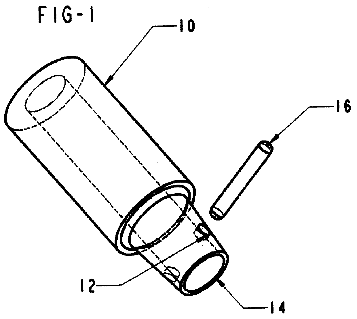
There is shown in FIG. 1 a preferred resistance welding electrode shank made in accordance with the present invention. The electrode shank 10 has a hole 12 which goes through the electrode shank 10 parallel to the top of the electrode shank 14 approximately 6 mm from the top of the electrode shank 14. The metal pin 16 inserted in hole 12.

The metal pin 16 should be manufactured from beryllium copper or beryllium nickel because both are high strength alloys that will not bend from the pressure of repeated impact during the resistance spot welding process. Furthemore, beryllium copper and beryllium nickel are both corrosion resistant alloys, which is necessary because the inside of the electrode shank 10 is continuously circulated with high pressure water as a cooling agent. Moreover, beryllium copper and beryllium nickel are high conductivity alloys that will not impair the low electrical resistivity and high current flow necessary for resistance spot welding.

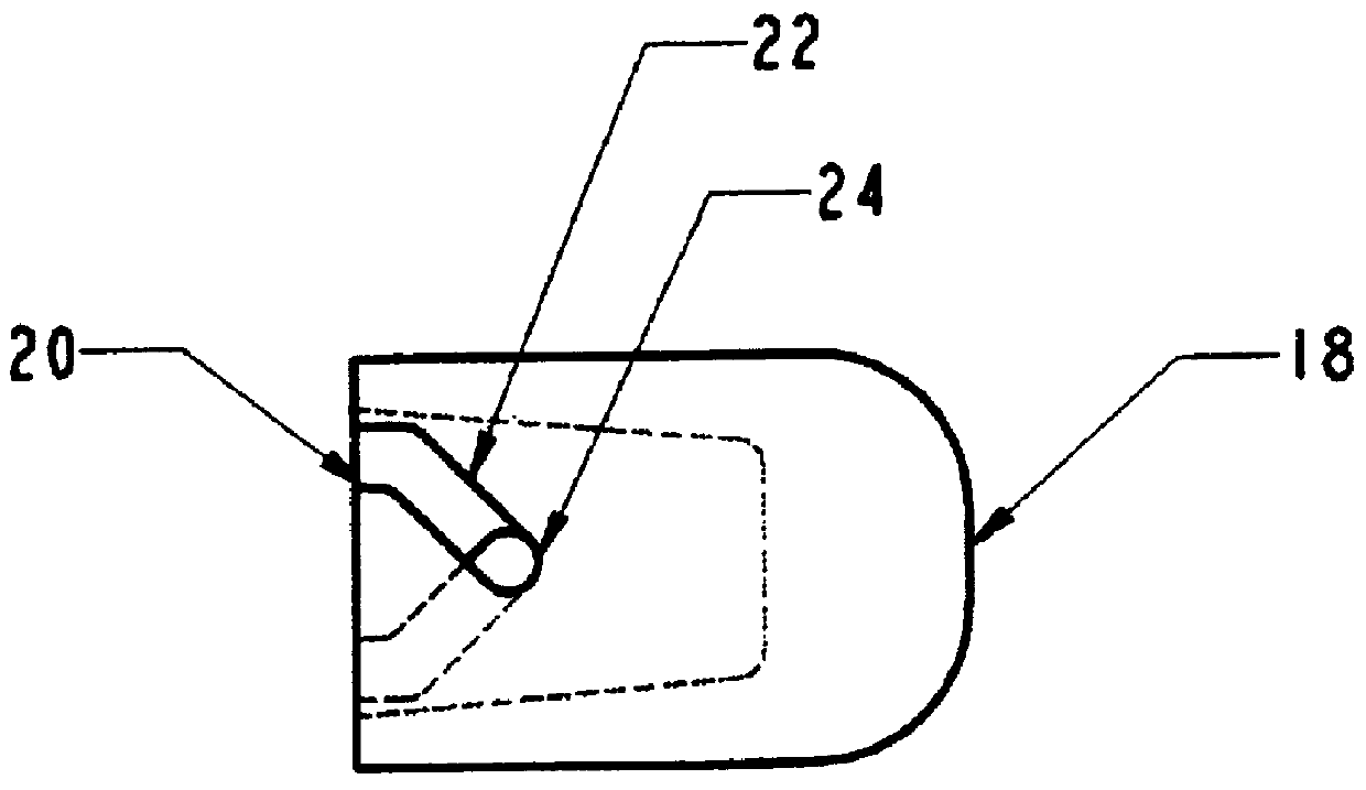
FIG. 2 illustrates the mo...


PUM

PropertyMeasurementUnit
Angleaaaaaaaaaa

Abstract

A resistance welding electrode body is fitted with a metal pin which serves as an anchor point for an electrode welding tip. The electrode welding tip contains two lead-in notches and diagonal grooves that allow the electrode tip to be locked onto the electrode body. This form of electrode has been found advantageous in terms of retaining the electrode tip onto the electrode body during resistance spot welding.

Description

1. Field of InventionThe present invention relates to electrodes used in resistance welding. The electrode tip has grooves that lock onto a metal pin which has been inserted in the electrode. The locking mechanism prevents workpiece metal from sticking to the tip; causing the tip to dislodge from the electrode. The locking mechanism eliminates the need for continuous reattachment of the electrode tip to the electrode and thereby facilitates production line flow and extends the useful life of the electrode.2. Description of Prior ArtResistance welding electrodes are widely used in industry for spot welding steel, aluminum, copper, and various other metals. Some particular applications are the assembly of automobile bodies and truck bodies. In each of these uses, a robot weld gun fitted with a pair of electrodes is moved in stages along a continuous weld path. At each stage, the electrodes are contacted with opposite sides of the workpieces to be welded, and an electric current is pas...

Claims


Application Information

Patent Timeline
IPC IPC(8): B23K11/30B23K35/02
CPCB23K11/3018B23K35/0205
Inventor YANG, DANIEL
Owner YANG DANIEL
Why Eureka
Try Eureka