Apparatus and method of atomizing and vaporizing

a technology of atomizing and vaporizing droplets, applied in the direction of spray nozzles, burners, lighting and heating apparatus, etc., to achieve the effect of quick vaporization, minimal slippage, and rapid vaporization of droplets

Inactive Publication Date: 2000-01-11
3M INNOVATIVE PROPERTIES CO
View PDF63 Cites 181 Cited by
  • Summary
  • Abstract
  • Description
  • Claims
  • Application Information

AI Technical Summary

Benefits of technology

The present invention provides a novel apparatus that causes a heated stream of gas to implosively and convergingly collide with at least one liquid stream in order to atomize and vaporize the liquid. Initially, the collision atomizes the liquid to form a mist of fine liquid droplets. The droplets, being in intimate contact with a relatively large volume of the gas, quickly vaporize with minimal slippage. Vaporization occurs quickly even at temperatures well below the boiling point of the liquid, because the partial pressure of the resultant vapor in the gas is well below the saturation pressure. Additionally, using implosive collision in this manner provides liquid droplets that have a smaller average droplet size with a narrower particle size distribution than atomized droplets obtained by using more conventional atomization devices. This capability is particularly beneficial in order to be able to quickly vaporize the droplets and then cause the resultant vapor to condense as a thin, substantially defect-free coating of uniform thickness upon any of a wide variety of substrates; although, in some cases discontinuous coatings can be intentionally made.

Problems solved by technology

Firstly, gas conveyed through the preheating chamber preheats liquid in the initial portion of the liquid passageway.

Method used


Image

  • Apparatus and method of atomizing and vaporizing
  • Apparatus and method of atomizing and vaporizing
  • Apparatus and method of atomizing and vaporizing

Examples


Embodiment Construction

The embodiments of the present invention described below are not intended to be exhaustive or to limit the invention to the precise forms disclosed in the following detailed description. Rather the embodiments are chosen and described so that others skilled in the art may appreciate and understand the principles and practices of the present invention.

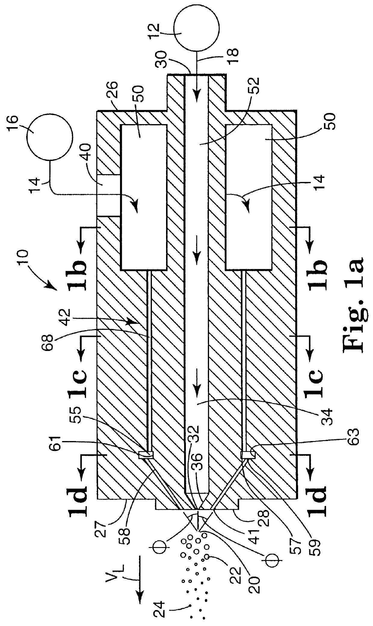
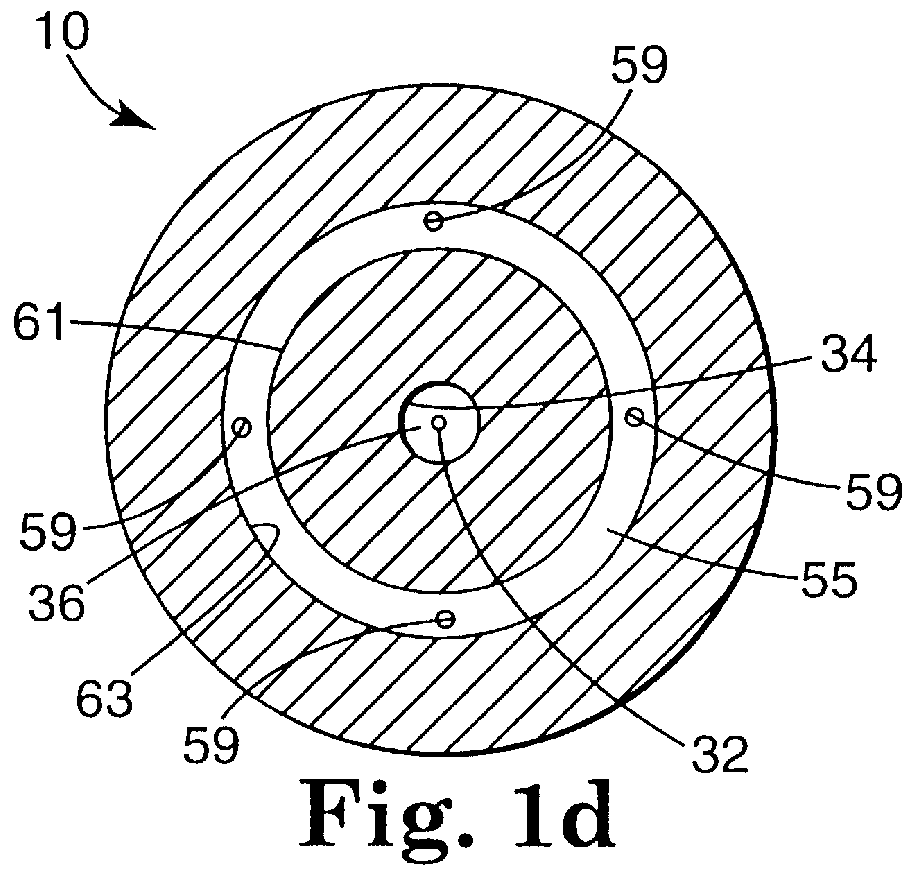
FIGS. 1a, 1b, 1c and 2 schematically show one representation of a preferred apparatus 10 of the present invention suitable for atomizing and vaporizing a liquid composition. Generally, apparatus 10 is structured to cause stream 14 of gas 16 to convergingly and implosively collide with stream 18 of liquid composition 12 at collision site 20 in front of apparatus 10. The implosive energy of the collision atomizes stream 18 of liquid composition 12 to form a plurality of atomized liquid droplets 22. Preferably, liquid droplets 22 have an average droplet size of less than 200 micrometers, preferably 10 to 100 micrometers, more preferably 10...


PUM


Abstract

Apparatus suitable for atomizing and vaporizing at least a first liquid by colliding at least one gas with the first liquid. The apparatus includes a gas inlet through which the gas enters the apparatus and a first liquid inlet through which the first liquid enters the apparatus. A discharge end of the apparatus includes at least one first liquid discharge outlet through which at least one stream of the first liquid is discharged from the apparatus. The discharge end also includes at least one gas discharge outlet through which at least one stream of gas is discharged from the apparatus to collide with and thereby atomize the discharged stream of the first liquid. A first liquid passageway interconnects the first liquid inlet with the first liquid discharge outlet. A gas passageway interconnects the gas inlet with the at least one gas discharge outlet. In one embodiment, the gas passageway comprises at least one gas chamber in thermal contact with an initial portion of the first liquid passageway such that a heated quantity of the gas in the chamber preheats the first liquid in the initial portion of the first liquid passageway. In alternative embodiments, the gas passageway includes a pressure dampening chamber allowing gas to be continuously discharged without pulsating.

Description

This invention is in the field of devices, such as a nozzle, that are structured to cause two or more streams of material to collide in front of the devices. More specifically, this invention relates to devices and related methods in which a stream of a gas is caused to collide with a stream of a liquid in order to atomize the liquid.Atomization is a process in which a liquid composition is broken up into a mist of fine liquid droplets. Atomization is involved in a wide range of industrial applications, including humidification processes, coating operations in which the atomized liquid composition is caused to form a coating on a substrate, vaporization processes, materials transport processes, inhalation delivery processes, and the like.Plain-jet, air blast atomization is an atomization technique in which a relatively high velocity gas stream is caused to collide with a stream of the liquid composition to be atomized. In a typical plain-jet, air blast atomization operation, streams...

Claims


Application Information

Patent Timeline
Patent Type & Authority Patents(United States)
IPC IPC(8): B05B7/06B05B7/02B05B7/24B05B7/16B05B7/08
CPCB05B7/066B05B7/162B05B7/2497B05B7/16
Inventor RUTA, CONSTANTIN I.BLETTE, RUSSELL E.LYONS, CHRISTOPHER S.FLEMING, ROBERT J.
Owner 3M INNOVATIVE PROPERTIES CO
Why Eureka
Try Eureka