Compressor impeller fastening for high speed turboengines

a compressor impeller and high-speed technology, which is applied in the direction of machines/engines, rotary propellers, liquid fuel engines, etc., can solve the problems of increasing the cost of compressor impellers, limiting the life of shaft/hub connections, and not being able to use compressor impellers with another shafts, etc., to achieve the effect of improving the fastening of compressor impellers, reducing the stress of the shaft, and widening the hub con

Inactive Publication Date: 2000-01-11
ABB TURBO SYST
View PDF24 Cites 42 Cited by
  • Summary
  • Abstract
  • Description
  • Claims
  • Application Information

AI Technical Summary

Benefits of technology

In a second embodiment of the invention, the hub cone is arranged on the compressor side of the mass center of gravity of the compressor impeller. The compressor impeller is thereby subjected to much less stress by centrifugal forces or thermal expansions than if the hub cone were arranged at the mass center of gravity. In this solution, which is particularly suitable for the external mounting of turbochargers, the widening of the hub cone can be reduced to an even greater extent and, consequently, the fasteni

Problems solved by technology

In this solution, the life of the shaft/hub connection is restricted due to the notches made by the female splines.
Moreover, additional centering elements are necessary, which increase the costs of the compressor impeller.
It is therefore not possible to use the compressor impeller with another shaft which is not balanced together with it.
This, however, is a decisive disadvantage in the event of servicing.
Production-related inaccuracies of the thread are likewise a disadvantage in these cases.
Moreover, the high operating torques occurring in compressor impellers necessitate high heightening and releasing torques.
However, this markedly increases the outlay necessary for

Method used


Image

  • Compressor impeller fastening for high speed turboengines
  • Compressor impeller fastening for high speed turboengines
  • Compressor impeller fastening for high speed turboengines

Examples


Embodiment Construction

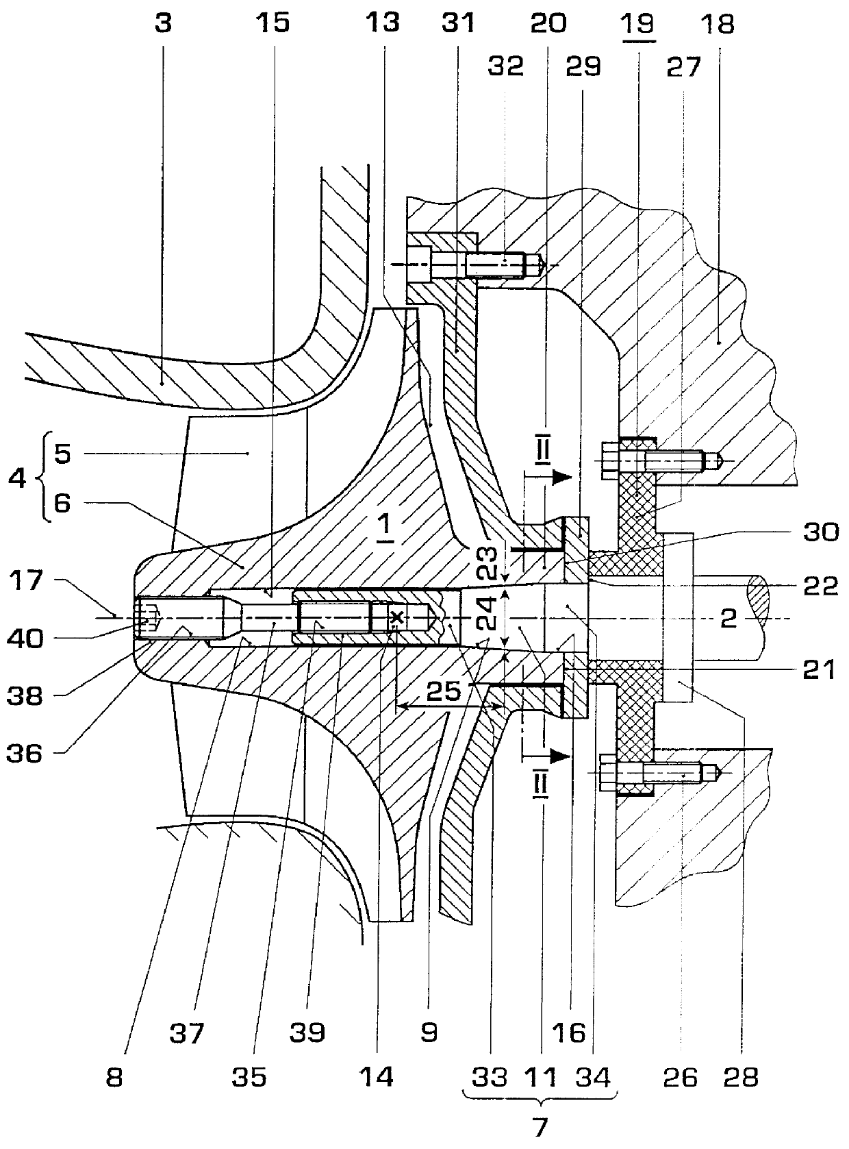
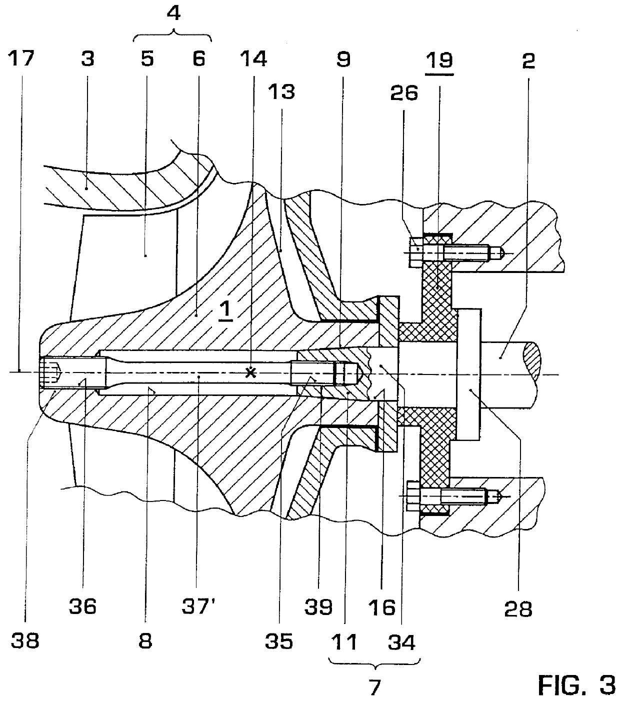
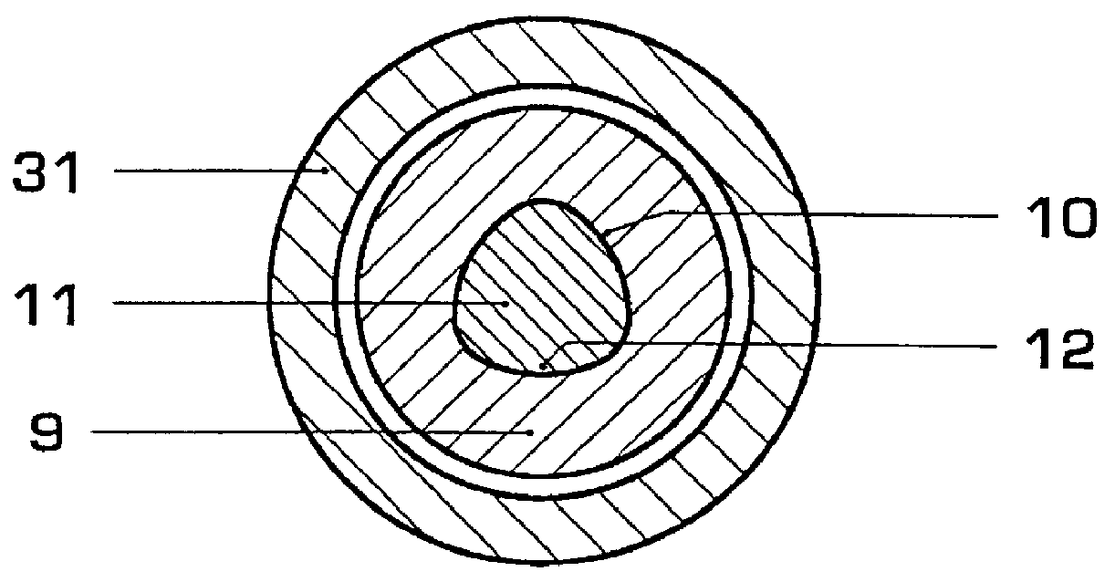
Referring now to the drawings, wherein like reference numerals designate identical or corresponding parts throughout the several views, the exhaust gas turbocharger consists mainly of a compressor 1 designed as a radial compressor and of an exhaust gas turbine, not illustrated, which are arranged on a common shaft 2. The radial compressor 1 possesses a compressor housing 3, in which a compressor impeller 4 is rotatably mounted on the shaft 2. The compressor impeller 4 has a hub 6 equipped with a multiplicity of moving blades 5. A central through bore 8 receiving a shaft journal 7 of the shaft 2 is made in the hub 6 (FIG. 1). The through bore 8 is designed partially as a hub cone 9 having a polygonal base area 10 (FIG. 2). The shaft journal 7 receives a shaft cone 11 which corresponds to the hub cone 9 and which itself likewise has a polygonal base area 12.

The hub 6 of the compressor impeller 4 is equipped on the shaft side with a rear wall 13. The compressor impeller 4 has a mass ce...


PUM


Abstract

The object of the invention is to provide a safe and reproducible compressor impeller fastening for high speed turboengines, which, moreover, possesses more accurate concentricity. This is achieved, according to the invention, in that both the hub cone (9) and the shaft cone (11) each have a mean diameter (23, 24) and these mean diameters (23, 24) are arranged at an axial distance (25) from the mass center of gravity (14) of the compressor impeller (4), said distance corresponding at least to half the mean diameters (23, 24). On the shaft side of the hub cone (9), the through bore (8) of the hub (6) is designed at least partially as a cylindrical bore (16).

Description

BACKGROUND OF THE INVENTION1. Field of the InventionThe invention relates to a compressor impeller fastening for high speed turboengines according to the preamble of claim 1.2. Discussion of BackgroundCompressor impellers of turboengines are connected to their driveshaft either nonpositively or positively. In the case of rising pressure ratios and consequently in the case of increasing operating torques and high circumferential speeds, positive torque transmission, that is to say a positive shaft / hub connection of the compressor impeller, is advantageous.EP 0,522,630 B1 discloses a positive compressor impeller fastening which is produced by means of a multispline shaft. In this solution, the life of the shaft / hub connection is restricted due to the notches made by the female splines. Moreover, additional centering elements are necessary, which increase the costs of the compressor impeller. Owing to the production-related inaccuracies of multispline shafts, such a shaft / hub connectio...

Claims


Application Information

Patent Timeline
IPC IPC(8): F01D5/02F02C6/12F04D29/28
CPCF01D5/025F04D29/266F05D2220/40F05D2230/70
Inventor BATTIG, JOSEFMULLER, ALFRED
Owner ABB TURBO SYST
Why Eureka
Try Eureka