Multi-layer structure and sensor and manufacturing process

a multi-layer structure and manufacturing process technology, applied in the field of magnetoresistive sensors, can solve the problems of limited sensitivity of these sensors and material properties deterioration

Inactive Publication Date: 2000-01-11
COMMISSARIAT A LENERGIE ATOMIQUE ET AUX ENERGIES ALTERNATIVES
View PDF4 Cites 48 Cited by
  • Summary
  • Abstract
  • Description
  • Claims
  • Application Information

AI Technical Summary

Problems solved by technology

Therefore the sensitivity of these sensors is limited.
However, the properties of...

Method used


Image

  • Multi-layer structure and sensor and manufacturing process
  • Multi-layer structure and sensor and manufacturing process
  • Multi-layer structure and sensor and manufacturing process

Examples


Embodiment Construction

Therefore the problem solved by this invention is to increase the thermal stability of the magnetoresistive material used in magnetoresistive sensors as much as possible, while maintaining good sensitivity of the material in weak fields. The increased thermal stability will also give a longer material life, and particularly better resistance to electromigration.

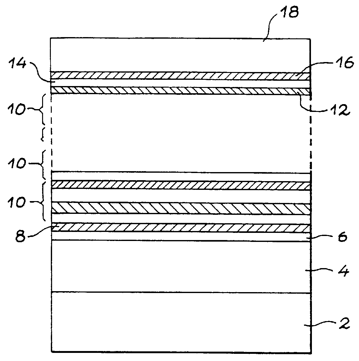
Thus the purpose of the invention is a magnetic layered structure comprising an alternate stack of:

layers of a first type, based on magnetic materials,

layers of a second type, made of Ag or an Ag rich alloy,

a thin interface layer of Co or a Co rich alloy being located at the interfaces between layers of the first type and layers of the second type.

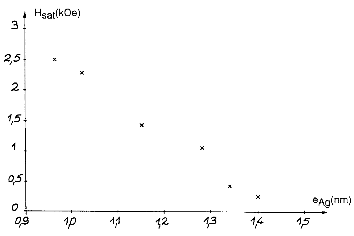
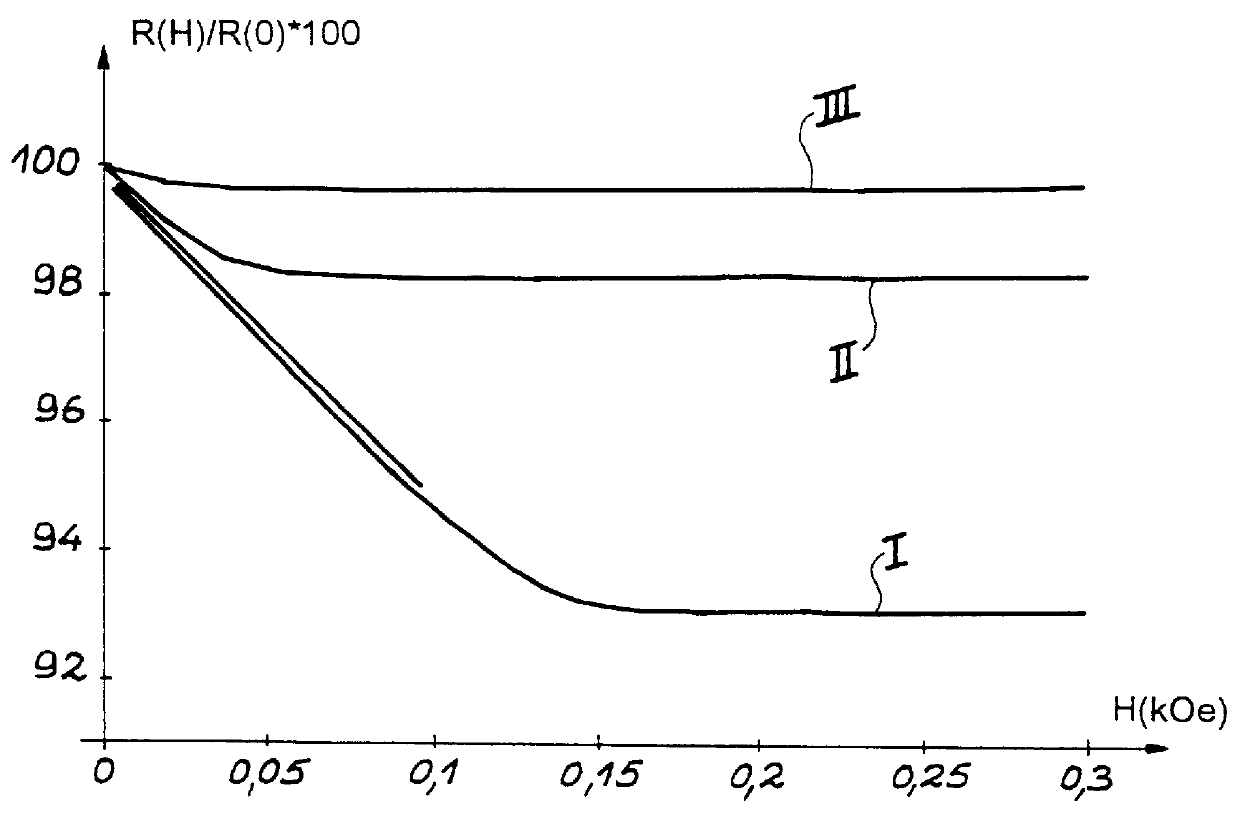
The effect of inserting the interface layer is to very significantly increase the structural stability of the material when subjected to annealing at up to 300.degree. C. for 20 minutes. A comparison of the effect of annealing a multi-layer with composition (NiFe 2.5 nm / Ag 1.1 nm).s...


PUM

PropertyMeasurementUnit
Thicknessaaaaaaaaaa
Thicknessaaaaaaaaaa
Thicknessaaaaaaaaaa

Abstract

This invention relates to a multilayered magnetic structure comprising an alternate stack of: layers (6, 16) of a first type based on magnetic materials, layers (12) of a second type, made of Ag or an Ag rich alloy, a thin interface layer (8, 14) of Co or a Co rich alloy being located at the interface between layers of the first type and layers of the second type. The invention also relates to a process for making this type of structure. Applications to sensors based on magnetoresistive effects, such as current sensors or magnetic heads.

Description

This invention generally relates to field detectors or magnetic flux detectors, and particularly to magnetoresistive sensors. Magnetoresistive sensors are used for example in magnetic recording to read information recorded on a magnetic information storage medium. More generally, the type of microsensor described in this invention relates to the detection of weak magnetic fields (typically within the range of 0.1 Oe to a few 10 s of Oe, i.e. from a few A / m to a few thousand A / m) Other application examples include determination of the electric current carried out by a conductor by measuring the magnetic field close to this conductor, position sensors (translation or rotation) or magnetoresistive compasses.STATE OF THE ARTUntil 1990, magnetoresistive sensors used for the detection of weak magnetic fields, particularly for use in magnetic recording, were based on the anisotropic effect of magnetoresistance. A detailed description of this effect is given in the article by D. A. Thompson...

Claims


Application Information

Patent Timeline
IPC IPC(8): G01R33/09G01R33/06H01F10/32H01F10/00G11B5/39H01L43/00H01L43/10G01R15/20H01F10/08
CPCB82Y10/00G01R15/205G01R33/093G11B5/3903H01F10/325H01L43/10B82Y25/00Y10T428/12806G11B2005/3996Y10T428/1291Y10T428/1129Y10T428/12465Y10T428/12861Y10T428/265Y10T428/115Y10T428/12896H10N50/85
Inventor DIENY, BERNARDAUFFRET, STEPHANECOWACHE, CHRISTOPHEBERTHET, FRANCK
Owner COMMISSARIAT A LENERGIE ATOMIQUE ET AUX ENERGIES ALTERNATIVES
Why Eureka
Try Eureka