Optical disc and method for producing same

Inactive Publication Date: 2000-01-18
SONY CORP
View PDF7 Cites 17 Cited by
  • Summary
  • Abstract
  • Description
  • Claims
  • Application Information

AI Technical Summary

Problems solved by technology

However, the laser of a shorter wavelength than 351 nm has as yet not reached the practically usable stage.
On the other hand, the value of NA of the objective lens currently used is also approaching the limit value that can be obtained in air, such that it is difficult to obtain the objective lens having the NA not less than 0.90.
Thus, it is feared that a master disc fabricating process which is in need of strict temperature and humidity control significantly different from that used heretofore needs to be introduced to render it extremely difficult to maintain operational stability.
The currently used master disc fabricating process experiences a problem that the width of a pit formed on light exposure depends on the pit length, such that the shorter the pit length, the narrower becomes the pit width.
However, if desired to produce a master disc for the optical disc higher in recording

Method used


Image

  • Optical disc and method for producing same
  • Optical disc and method for producing same
  • Optical disc and method for producing same

Examples


Embodiment Construction

Referring to the drawings, preferred embodiments an optical disc and its manufacturing method according to the present invention will be explained in detail.

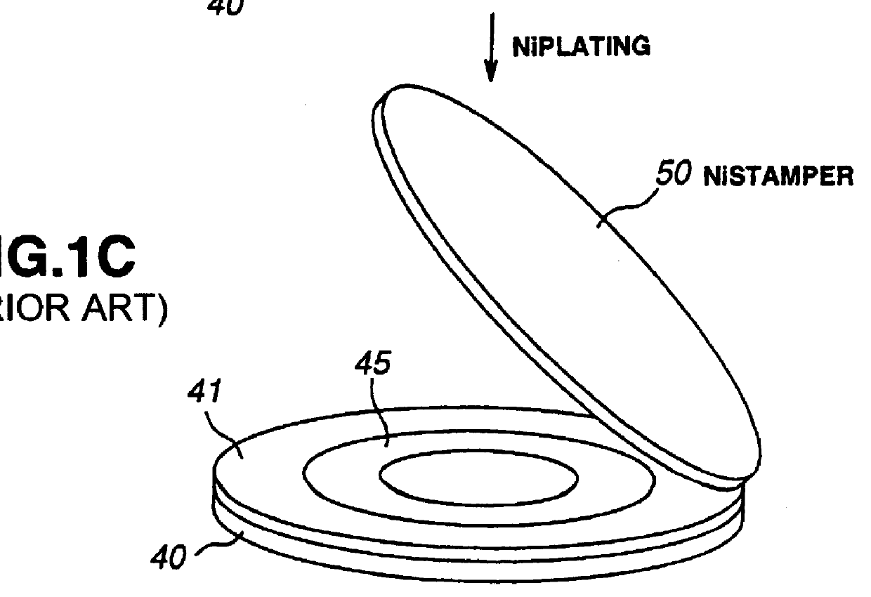
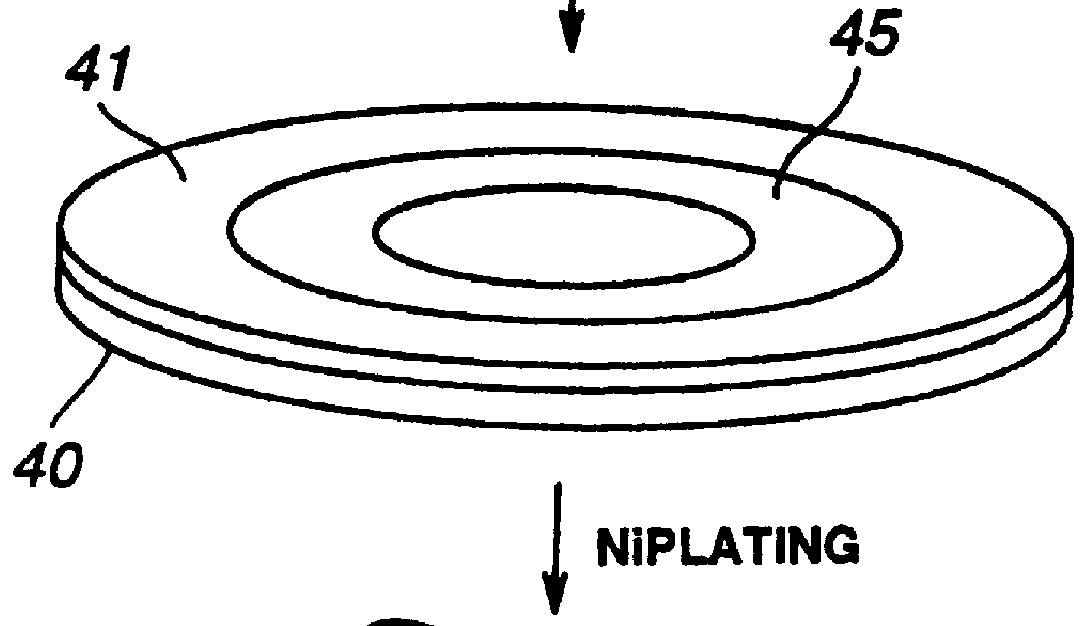
FIGS. 1A-1C and 2A-2C illustrate a conventional method for producing an optical disc.

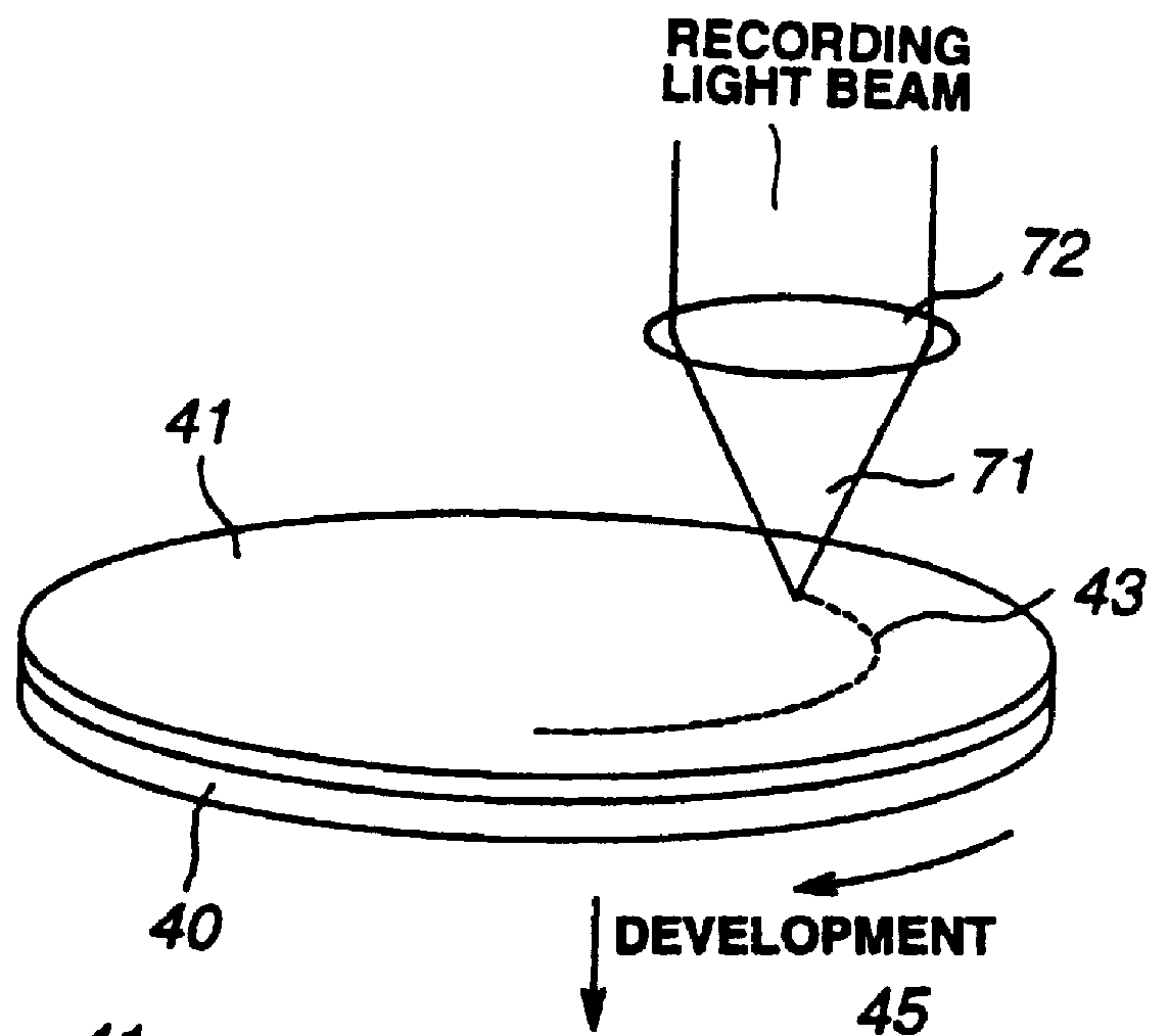
Referring first to FIG. 1a, a photoresist layer 41, coated on a circular glass master disc 40, having its surface sufficiently polished to a planar surface and rinsed, is exposed to light by a recording light beam 71 converged by an objective lens 72, in accordance with recording signals, for forming a latent image 43 of the row of pits. This light exposure step is termed laser cutting because the laser is used as the recording light beam 71.

The light converging position of the recording light beam 71, intermittently illuminated depending on the recording signals, is radially fed, as the glass master disc 40 is rotated, an equal distance per revolution of the glass master disc 40, for spirally forming a row of pits at a constant interval (track ...


PUM


Abstract

An optical disc having pits shorter in length than 0.40 mu m, with the ratio of the width of the shortest pit to that of the longest pit being not less than 0.8, is formed by forming a master disc by light exposure using a light source having a wavelength not shorter than 350 nm. By taking advantage of the fact that the pit width A looking from the reflective film 20 of the optical disc is deceased to be smaller on forming the reflective film 20 than the pit width B looking from the disc substrate 10 by a value equal to the film thickness, a row of pits, generally broader than the pit width optimum when looking from the side oft the disc substrate 10, is formed on light exposure on the master disc using the laser light having a wavelength not smaller than 350 nm. The reflective film 20 is formed on the row of pits transcribed from the master disc to the disc substrate 10 to provide a pit width which minimizes the inter-pit interference or jitter of the playback RF signals. The signals are read out from the side of the reflective film 20, that is from the side of the light-transmitting layer 30, instead of from the light-transmitting layer 30.

Description

1. Field of the InventionThis invention relates to an optical disc produced using a master disc having signals recorded thereon on light exposure, and a manufacturing method thereof.2. Related ArtAn optical disc, as a recording medium for recording signals to high density, is fabricated by stamping of the crests and recesses of a master disc corresponding to signals by, for example, injection molding. For raising the recording density of the so-produced optical disc, it is necessary to shorten the wavelength of the recording light used for forming the crests and recesses corresponding to the recording signals by light exposure on the master disc.For forming pits by light exposure on a master disc of a digital video disc (DVD) having a recording density not less than five times that of a compact disc (CD), the Ar or Kr laser having a wavelength of 351 nm is used. In an optical system for converging the laser for light exposure, an objective lens having a numerical aperture (NA) of th...

Claims


Application Information

Patent Timeline
IPC IPC(8): G11B7/013G11B7/26G11B7/007G11B7/24073G11B7/24079G11B7/24085
CPCG11B7/24085G11B7/263G11B7/007
Inventor YAMATSU, HISAYUKIKASHIWAGI, TOSHIYUKIIMANISHI, SHINGOMASUHARA, SHIN
Owner SONY CORP
Why Eureka
Try Eureka