Flexible tubular conduit

a tubular conduit and flexible technology, applied in the direction of flexible pipes, pipes, rigid pipes, etc., can solve the problems of increasing costs, crushing resistance of the shaped tubular layer and the flexible tubular conduit incorporating this layer may prove insufficient, etc., to achieve low production cost, reduce costs, and high resistance to crushing

Inactive Publication Date: 2000-01-25
COFLEXIP
View PDF20 Cites 49 Cited by
  • Summary
  • Abstract
  • Description
  • Claims
  • Application Information

AI Technical Summary

Benefits of technology

The present invention proposes to make a flexible tubular conduit which will have especially a high resistance to crushing, while still being able to be carried out at low production costs. In addition to the cost reduction obtained by easier and quicker manufacture, the present invention also aims to reduce the weight of the tubular layer for a given crushing resistance making it possible, on the one hand, to reduce the weight and the cost of the raw materials used in manufacture, and on the other hand to achieve flexible conduits which can be used in greater depths of water.
Thus, when the strip is in the wound state, there exists between each of the principal spans of a spiral and a principal span of the adjacent spiral a crush-resistant structure due to a double thrust of the end section and of the connecting section of the second secondary span against the first principal span of the adjacent spiral and of the flexural rigidity conferred by the looped intermediate section. The thrust of the looped intermediate section against the first secondary span of the spiral which is itself in contact with the second principal span of the spiral in question, makes it possible to further increase the rigidity of the shaped strip by providing an arched supporting effect, the middle portion of the looped intermediate section being able to have a rounded cross section or to have a cylindrical central span.

Problems solved by technology

Consequently it has been found that the resistance to crushing of the shaped tubular layer and of the flexible tubular conduit incorporating this layer may prove insufficient when the mechanical stresses which it must withstand are great, particularly in applications where a high pressure is applied to the exterior of the conduit.
As a result of the very close tolerances thus imposed on the finished product, the industrial production has to be performed with a special care which increases costs.

Method used


Image

  • Flexible tubular conduit
  • Flexible tubular conduit
  • Flexible tubular conduit

Examples


Embodiment Construction

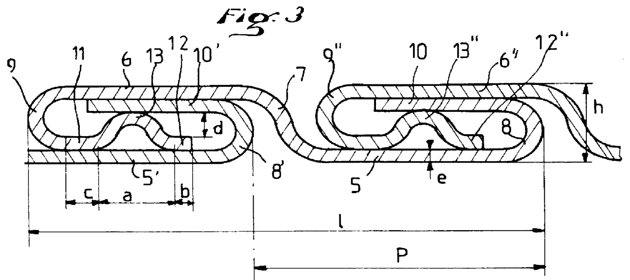
has a molded strip width of 16 mm, with a thickness b of the tubular layer of 3.5 mm, or 5 times the thickness , instead of 4.2 mm in Example 1.

It has been found that Example 1a offers a crush resistance of only 60.8 bars, against 79 for Example 1. A conduit using the shaped or profiled strip according to the invention can therefore, in the present case, be used in about 30% greater depths of water without increase of the amount of material used in making the tubular layer constituting its inner body.

Furthermore, the pitch is only 9.7 mm for Example 1a, instead of 13.3 mm. The rate at which the flexible metal tube is produced by the winders commonly used being normally proportional to the pitch of the helix formed by the interlocking strip, the length of time for the continuous production of a tube according to the invention is therefore, in this case, 27% shorter than for the equivalent tube of the prior art, representing a great reduction of t he cost of manufacture.

In the case of...


PUM


Abstract

The invention relates to a flexible tubular conduit having at least one tubular layer constituted by at least one molded strip of a cross section substantially in the form of an elongated S, wound helically and having a cross section formed of a first and of a second principal cylindrical coaxial spans joined together by an inclined central portion, each of the first and second principal cylindrical spans being united by a first convex radial portion to a first secondary cylindrical span and by a second convex radial portion to a second secondary span. The second secondary span comprises a section connecting to the second convex radial portion (9), an end section (12) and a like intermediate section (13) whose concavity is turned away from the second principal span (6), and the second secondary span (12, 13) is arranged such that, when the strip is in the wound state, the connecting section is thrusting against the first principal span (5') of an adjacent spiral, and the end section (12) applies itself to the said first principal span (5')

Description

The present invention relates to a flexible tubular conduit of the type having at least one tubular layer constituted by at least one shaped band of a cross section substantially in the form of an elongated S, helically wound with a small pitch and with its successive spirals interlocked.The applicant company has for many years manufactured and sold flexible tubular conduits of great length, of high mechanical strength, useful particularly for carrying hydrocarbons, particularly in connection with undersea petroleum producing installations.Such flexible conduits generally comprise a tubular layer constituted by a double-interlocking strip, this layer being able to constitute the internal body of the flexible conduit in "rough bore" type conduits, an armor designed to give the flexible tubular conduit great resistance to internal pressure and to traction, an intermediate sealing sheath and, if necessary, an external protective sheath.In conduits of the "smooth bore" type the intermed...

Claims


Application Information

Patent Timeline
Patent Type & Authority Patents(United States)
IPC IPC(8): F16L11/04F16L11/08F16L11/00F16L11/16F16L11/10
CPCF16L11/083F16L11/10F16L11/16
Inventor JUNG, PATRICELE BAIL, GUY
Owner COFLEXIP
Why Eureka
Try Eureka