Inking device for a rotary printing machine

Inactive Publication Date: 2000-02-15
MANROLANAD AG
View PDF18 Cites 21 Cited by
  • Summary
  • Abstract
  • Description
  • Claims
  • Application Information

AI Technical Summary

Problems solved by technology

A disadvantage of the inking device known from DE 39 11 839 A1 is that ink supplied from the ink application channel but not absorbed by the cups of the screen roller is not fed back to the ink supply system and is lost.
The disadvantage of this ink supply system is that it is open.
When the ink is sprayed out, not only are the inking device rollers inked

Method used


Image

  • Inking device for a rotary printing machine
  • Inking device for a rotary printing machine

Examples


Embodiment Construction

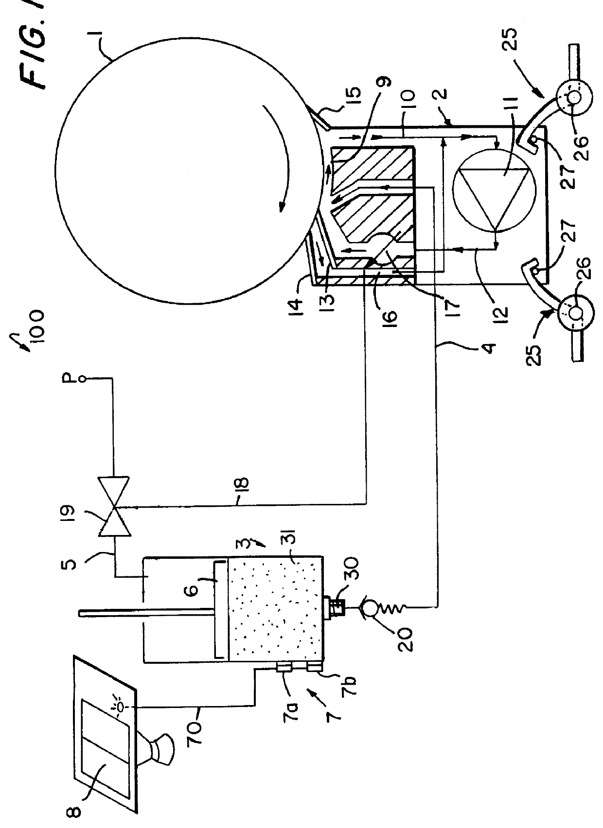
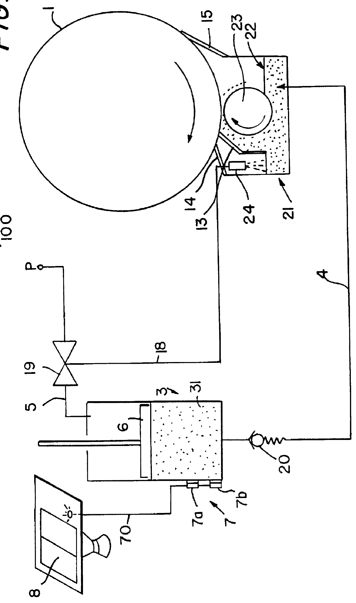
Referring initially to FIG. 1, an inking device 100 for a printing machine (not shown) includes a roller 1 that is inked by an ink supply device 2. The roller 1 comprises a screen roller with cups or hatchings and belongs to a short inking unit. In the preferred embodiment, the roller 1 rotates at machine speed of the printing machine in which the inking device is mounted (machine speed is determined by the speed of a form cylinder of the printing machine (not shown)). The width of the ink supply device 2 is preferably the same as the width of the printing stock web. However, if the printing web is 4-pages wide, the ink supply device 2 may also be 1-page wide or 2-pages wide. Ink supply devices 2 of different page widths are thereby interchangeable with each other. The ink supply device 2 is supplied with printing ink from an ink reservoir 3 via a supply line 4. The ink reservoir 3 preferably has a manually exchangeable ink cartridge 31. The ink reservoir 3 may be directly attached ...


PUM


Abstract

An inking device for inking a screen roller of a printing machine includes an ink supply device with an ink reservoir that are removable as one unit from the printing machine easily and without tools. The ink reservoir is separable from the ink supply device. The ink reservoir is filled using an ink cartridge. The printing ink is conveyed under pressure from the ink reservoir to the ink supply device in a supply line. The ink is pressed into the cups or hatchings of the inking device roller via the supply line by using a pump or a conveying roller.

Description

1. Field of the InventionThe invention relates to an inking device for a rotary printing machine with a screen roller having an ink supply device arranged on the screen roller. The ink supply device is sealed by blades positioned parallel to a longitudinal axis of the screen roller. The ink supply device supplies printing ink to the circumferential surface of the screen roller and carries away ink that is unabsorbed by or wiped away from the screen roller.2. Description of the Related ArtA prior art rinsing inking device for a rotary printing machine is disclosed in German reference DE 39 11 839 A1. The prior art rinsing inking device interacts with a screen roller. A closed chamber is arranged below the screen roller bounded by blades on both sides on a circumferential surface of the screen roller. A supply device positioned between the two blades inside the chamber for supplying printing ink under a slight overpressure in an ink application channel. The edges of the supply device ...

Claims


Application Information

Patent Timeline
IPC IPC(8): B41F31/08B41F9/00B41F9/06B41F31/02B41F31/20
CPCB41F9/061B41F31/08
Inventor DILLIG, PEERSCHONBERGER, WOLFGANG
Owner MANROLANAD AG
Why Eureka
Try Eureka