Normally white twisted nematic liquid crystal display including retardation films for improving viewing characteristics

a technology of retardation film and liquid crystal display, which is applied in non-linear optics, instruments, optics, etc., can solve the problems of severe color shift for both saturated and gray scale colors, limiting the contrast achievable in these lcds by the amount of light which leaks through the display, and limiting the contrast by the amount of light which leaks

Inactive Publication Date: 2000-02-22
GUARDIAN IND CORP
View PDF62 Cites 24 Cited by
  • Summary
  • Abstract
  • Description
  • Claims
  • Application Information

AI Technical Summary

Problems solved by technology

In normally black liquid crystal displays, the primary factor limiting the contrast achievable in these LCDs is the amount of light which leaks through the display in the darkened or OFF state.
In normally white (NW) LCDs, the primary factor limiting the contrast is the amount of light which leaks through the display in the darkened or ON state.
These problems are compounded in a bright environment, such as sunlight, where there is a considerable amount of reflected and scattered ambient light.
In color liquid crystal displays, light leakage causes severe color shifts for both saturated and gray scale colors.
These limitations are particularly important for avionic applications, where the copilot's viewing of the pilot's displays is important.
Therefore, normally black liquid crystal displays must be manufactured in accordance with rather specific tolerance parameters related to the cell gap of the display making them both difficult and expensive to make.
This increases, of course, the difficulty and expense of manufacturing this type of LCD.
However, while normally white LCDs are less sensitive to temperature and cell gap than normally black LCDs, their contrast ratios at large viewing angles are generally small relative to those of normally black displays.
The phase retardation effect such a liquid crystal material has on light passing through it inherently varies or increases with the inclination angle of light, leading to lower contrast ratios and a lower quality image at larger viewing angles.
The problem of ostensibly dark areas appearing light or colored when viewed at large angles still occurs, however, thereby creating the aforesaid lo

Method used


Image

  • Normally white twisted nematic liquid crystal display including retardation films for improving viewing characteristics
  • Normally white twisted nematic liquid crystal display including retardation films for improving viewing characteristics
  • Normally white twisted nematic liquid crystal display including retardation films for improving viewing characteristics

Examples


first embodiment

FIG. 11(a) is a schematic view of the optical components and their respective orientations of this invention. As shown in FIG. 11(a) the normally white "X-buffed" LCD (or pixel) of this embodiment discloses a rear linear polarizer 1 provided at the light incident side of the liquid crystal layer 5, an exit or front linear polarizer 9 provided at the light exit side of the liquid crystal layer 5, a rear retardation film or plate 3 provided between the liquid crystal layer and the rear polarizer 1, and a front retardation film or plate 7 provided between the liquid crystal layer 5 and the front linear polarizer 9. The retardation films of this embodiment preferably are uniaxial and have positive birefringent (.increment.N) values. An example of uniaxial positively birefringent retardation films useful in the practice of this invention are films commercially available from, for example, Nitto Corp., Japan, or Nitto Denko America, Inc., New Brunswick, N.J., as Model No. NRF-RF120 (120 n...

example 1

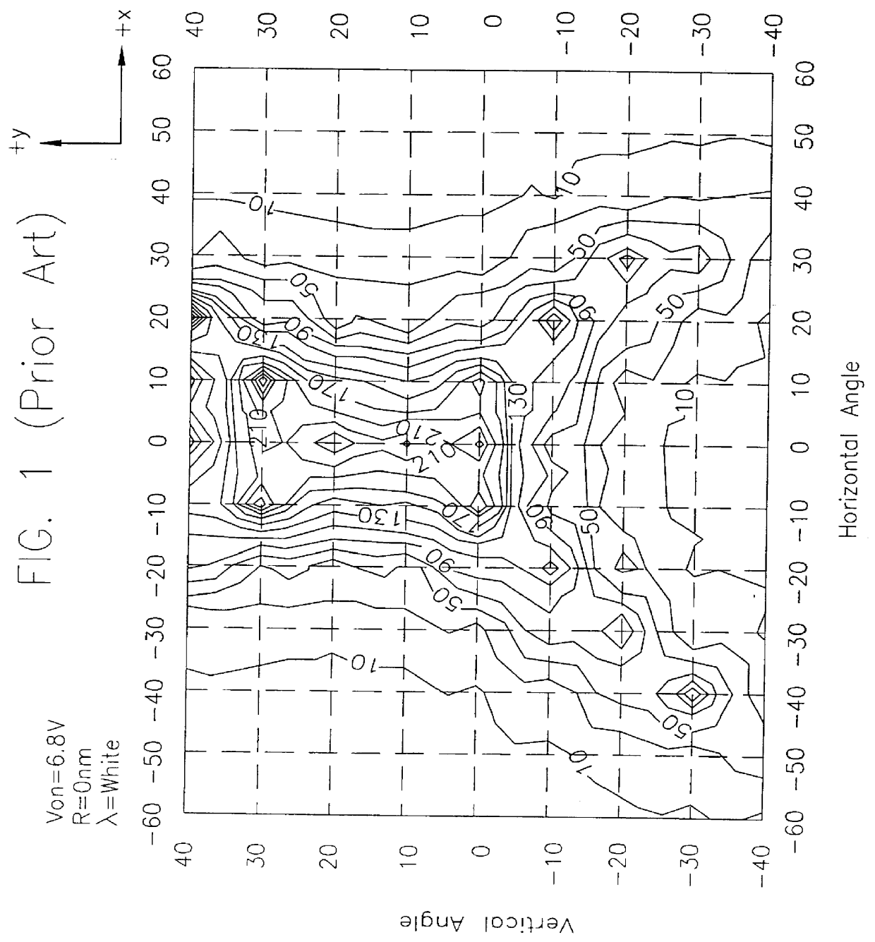
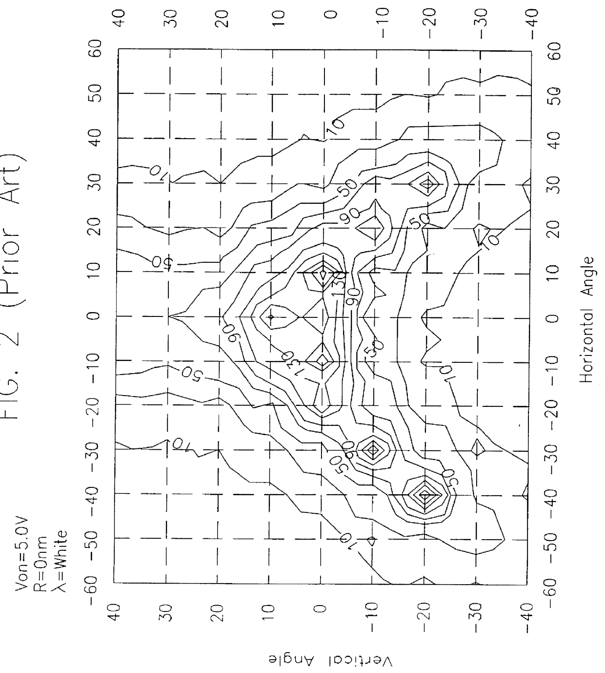
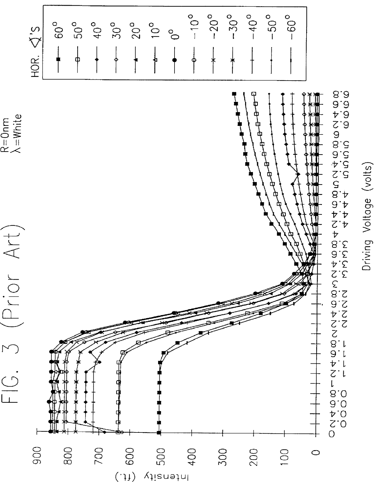
In this first example, an "X-buffed" light valve having a cell gap "d" of 5.86 .mu.m and a liquid crystal birefringence (.increment.N) of 0.084 at room temperature was manufactured and tested as follows. The liquid crystal material used is available commercially from E. Merck Ltd. or its U.S. representative EM Industries, Inc., Hawthorne, N.Y. as Model No. ZLI4718. Data resulting from the light valve of this example is illustrated in FIGS. 26-30.

The light valve pixel of this example was similar to the first embodiment of this invention in that the rear linear polarizer had a transmission axis direction about parallel to the optical axis of the rear retardation film, and the optical axis of the front retardation film was about parallel to the transmission axis of the front or exit linear polarizer. The orientation or buffing direction of the rear orientation film was approximately perpendicular to the optical axis of the rear retardation film, and was approximately parallel to the op...

example 2

In this second example, a multi-colored liquid crystal display utilizing TFTs as switching devices in an active matrix array was constructed as follows. The normally white "X-buffed" liquid crystal display had a cell gap "d" of about 5.1 .mu.m for the red subpixel which included a red color filter, and a cell gap "d" of about 5.7 .mu.m for the green and blue subpixels which included green and blue color filters respectively. The difference in cell gap for the different subpixels was due to the different thicknesses of the color filters. The birefringence of the LC material was 0.084 at room temperature. The liquid crystal material was purchased from Merck, Model No. ZLI4718. The display had a rear linear polarizer having a transmission axis substantially perpendicular to the transmission axis of the front or exit linear polarizer. A rear retardation film having an optical axis about parallel to the transmission axis of the rear polarizer was sandwiched between the rear polarizer and...


PUM


Abstract

A liquid crystal display in which a negatively birefringent layer is used as both an orientation film and as a retarder in the display. An improved method of making such a display is also disclosed. In preferred embodiments, each of the orientation layers has a retardation value of from about -80 to -200 nm.

Description

This invention relates to a liquid crystal display having at least two retardation films, one on each side of a liquid crystal layer. More particularly, this invention relates to a normally white liquid crystal display which includes at least one retardation film having a retardation value of 80-200 nm on each side of the liquid crystal layer.RELATED PATENTSThis application is related to commonly owned U.S. Pat. Nos. 5,706,068; 5,570,214; 5,694,187; 5,657,140; 5,576,861; and 5,594,568, the disclosures of which are hereby incorporated herein by reference.Liquid crystal materials are useful for electronic displays because light traveling through a layer of liquid crystal (LC) material is affected by the anisotropic or birefringent value (.increment.N) of the material, which in turn can be controlled by the application of a voltage across the liquid crystal material. Liquid crystal displays are desirable because the transmission or reflection of light from an external source, including...

Claims


Application Information

Patent Timeline
IPC IPC(8): G02F1/13G02F1/1337G02F1/1335G02F1/139G02F1/13363
CPCG02F1/13363G02F1/133634G02F1/133784G02F1/1396G02F2001/133531G02F2202/40G02F2413/02G02F2413/08G02F1/133531
Inventor ABILEAH, ADIELXU, GANGZHONG, JOHN Z. Z.
Owner GUARDIAN IND CORP
Why Eureka
Try Eureka