Enantiomorphic friction-stir welding probe

Inactive Publication Date: 2000-02-29
C INNOVATIONS
View PDF3 Cites 91 Cited by
  • Summary
  • Abstract
  • Description
  • Claims
  • Application Information

AI Technical Summary

Benefits of technology

It is an object of this invention to provide an improved friction-st

Problems solved by technology

Also, as currently developed, the speed of welding is slower than and the welding equipment is not as portable as that for other welding processes.
However, Thomas, et al. do not disclose any details of probe surface morphology and,

Method used


Image

  • Enantiomorphic friction-stir welding probe
  • Enantiomorphic friction-stir welding probe

Examples


Embodiment Construction

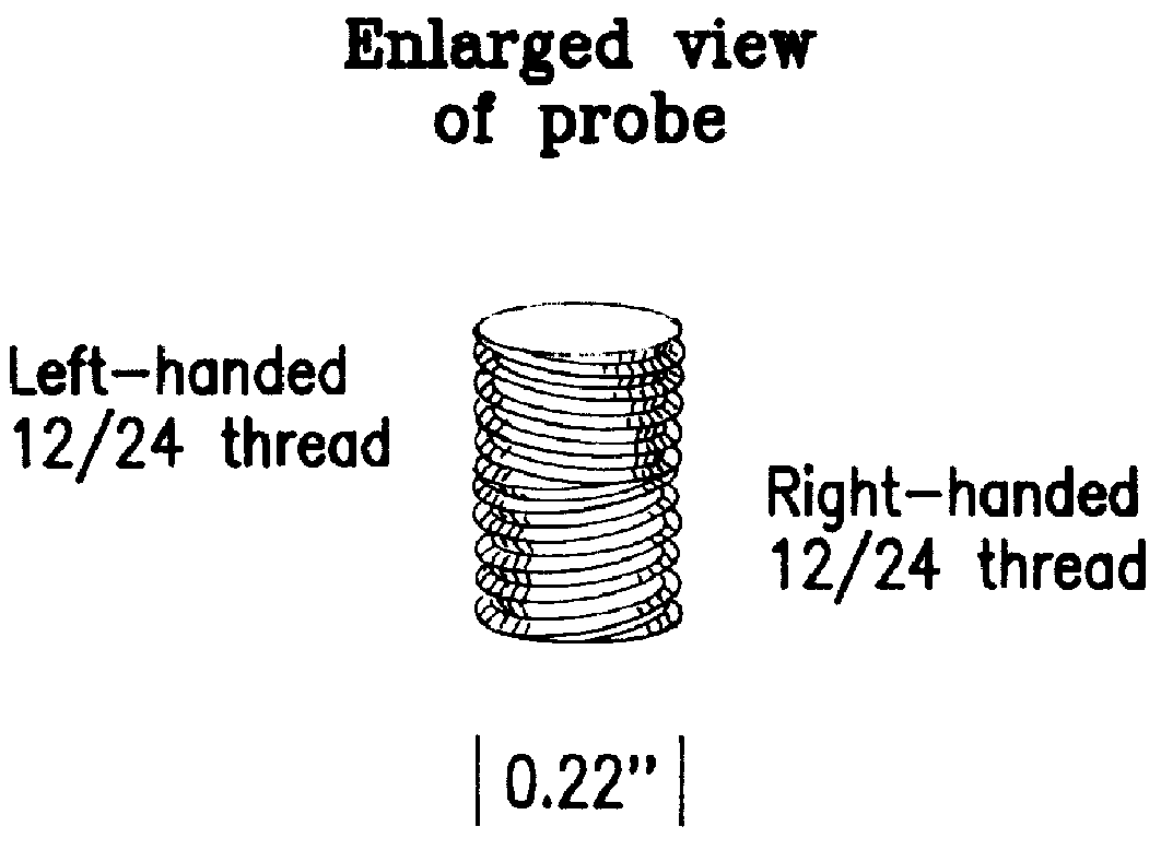
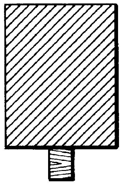
In a preferred embodiment, a tool steel rod was machined to have a shoulder portion for attachment by gripping that is 3 / 4 of an inch in diameter and 1 inch in length. The rod was further machined at one end to form a probe that was 0.22 inches in diameter and 1 / 4 of an inch in length, this probe being connected to the shoulder portion to render easier the attachment of the probe to a milling machine. The surface morphology of this probe region was made with an upper portion having size 12 / 24 left-handed machine threads and a lower portion having size 12 / 24 right-handed machine threads. The relationship of this surface morphology was thus an enantiomorphic one. This probe was used to friction-stir weld two plates of 6061 aluminum alloy, 7 inches in length by 3 inches in width by 1 / 4 of an inch in thickness, which were affixed to the table of a milling machine with the 7 inch sides flush with one another. The shoulder rod of the enantiomorphic friction-stir welding probe were placed ...


PUM

PropertyMeasurementUnit
Yield strengthaaaaaaaaaa

Abstract

A friction-stir welding probe tip is disclosed which has right-handed threads on one portion of the probe and left-handed threads on another portion of the probe such that weld material is drawn to the middle of the weld as the friction-stir welding probe is rotated and passed along the joint region of the pieces to be joined. This probe tip is also fitted with a shoulder region for gripping by a rotation means.

Description

This invention relates to friction-stir welding, and more particularly to the probe used in the friction-stir welding process.Welding became a developed means of joining metals during World War I and has since expanded to become one of the most widely used joining techniques. It is commonly applied in applications in which leak-tightness is important, as in containers or conduits for liquids or gases, such as ships or pipelines. Welding generally involves local melting of the materials to be welded with or without the application of pressure; cold welding is also possible using high pressure rolling or hammering. The heat needed in hot-welding is typically generated using electric current as in resistance welding, including seam welding and spot welding, or in electric arc welding. Melting can also be accomplished with a gas flame as in fusion welding with an oxyacetylene torch.The technique of using heat generated by friction has been found to produce a combination of metal deforma...

Claims


Application Information

Patent Timeline
IPC IPC(8): B23K20/12
CPCB23K20/1255
Inventor COCKS, ELIJAH E.
Owner C INNOVATIONS
Why Eureka
Try Eureka