System and method for ultrasonic cleaning and degreasing

a technology of ultrasonic cleaning and degreasing, applied in the direction of cleaning process and equipment, cleaning process using liquids, chemistry apparatus and processes, etc., can solve the problems of reducing the effective energy transported to the part being cleaned within the beaker, affecting the movement of the beaker/template/tub combination, and wasting the ultrasonic energy produced by the ultrasonic bath. , to achieve the effect of increasing the total ultrasonic energy transmitted, increasing the mass or

Inactive Publication Date: 2000-02-29
RUSCZYK LESTER LEE
View PDF11 Cites 15 Cited by
  • Summary
  • Abstract
  • Description
  • Claims
  • Application Information

AI Technical Summary

Benefits of technology

1. Provide a method to improve the cavitation of an ultrasonic cleaning fluid contained within an ultrasonic cleaning bath;
Note that one significant disadvantage of methods taught by Runnells and others is the effect of nodes ("dead spots") within the ultrasonic bath, in which ultrasonic activity is at a minimum, resulting in little or no cavitation. The presently disclosed invention permits "dummy" ballasts to be placed within the ultrasonic bath so as to position ballast / vessel combinations judiciously at the ultrasonic anti-nodes (regions of high amplitude ultrasonic activity) within the bath, and thus affect maximum cavitation in the cleaning fluid surrounding the cleaning target without restricting the rotation of the cleaning target within the ultrasonic bath fluid. Also note that by reducing the dampening of ultrasonic harmonics within the bath fluid, the present invention tends to mitigate the effects of ultrasonic standing wave nodes within the bath fluid, thus providing a solution to a problem in the field of ultrasonics which has usually been attacked by making modifications to the ultrasonic energy source and / or the ultrasonic tank.

Problems solved by technology

The major deficiency in the Runnells implementation is in the mechanical connection of the retaining template (104) for retaining the glass beakers (107, 108) to the support basket (103).
This mechanical linkage means that some of the ultrasonic energy which is produced by the ultrasonic bath is wasted to affect movement of the beaker / template / tub combination, rather than being used to produce cavitation surrounding the cleaning target.
Unfortunately, this configuration is functionally identical to that of the Runnells retaining template (104) in FIG. 1, with the exception that the Obermiller device supports more containment vessels.
This results in a movement of the beaker and a reduction in effective energy transported to the part being cleaned within the beaker.
The field of art surrounding this patent does not pertain to the ultrasonic cleaning art and furthermore cooler devices are inherently poor transmitters of both thermal and ultrasonic energy, making this device and its variants unsuitable for use in ultrasonic cleaning applications.
As such, this approach increases the overall total mass of the flotation device and results in a system which would be unsuitable for use in the ultrasonic cleaning arts.
Furthermore, Nolte specifically discloses isolation of the bowl from the surrounding liquid support surface, making the teachings of this device inappropriate for ultrasonic cleaning applications.
There are major technological issues which are problematic with the current technology of ultrasonic cleaning, which include among others the following:
This presents a problem in that many of the newer cleaning fluids are not as effective as their previous toxic counterparts.
One significant issue related to that of the environment involves cleaning of medical instruments, dental appliances, and the like which later come in contact with the human body.
In these circumstances the use of toxic cleaning agents is eschewed, as residue may be detrimental to any human who later comes in contact with the cleaning target.
Unfortunately, any cleaning agent will be ultimately limited in its effectiveness by the efficiency of the ultrasonic cleaning system in which it is used.
Current technologies as described by Runnells and others fail to consider this problem in their design.
Current technologies make this difficult, and in essence require that a glass or plastic beaker be discarded along with each batch of cleaning fluid that is contaminated with biohazard waste.
Both of these approaches (and combinations of them) fail to adequately service many applications, as the amount of harmonic energy imparted to the cleaning target is substantially attenuated by any materials in the ultrasonic tub which may dissipate or be receptive to these harmonics.
Thus, energy which could be used to cavitate the cleaning target surface is wasted and not applied to the cleaning process.
This situation restricts the effective cleaning of conventional ultrasonic systems in that to achieve high ultrasonic harmonic excitation amplitudes quickly requires fundamental power levels which are too large to practically generate.
A significant problem with both these approaches is that of increased cost.
Variations of this have included increasing use of harmonics and the like, but nothing has been done to affect more efficient use of the ultrasonic energy to promote faster and more efficient cleaning of the cleaning target.
These heaters require additional energy to be active, and result in additional system losses which reduce overall energy efficiency.
First, existing ultrasonic systems are operated inefficiently from an energy conservation point of view, in that they consume energy which does not directly contribute to cavitation and thus is wasted during the cleaning process.
An issue related to that of energy conservation is that of time conservation.
In many circumstances the power consumption of a given ultrasonic system is constant.
), there is a net energy loss associated with the degassing process which is proportional to the size of the ultrasonic cleaning tank.
This energy loss results in no effective processing of the cleaning target and is primarily a preliminary process which must be used to prepare the cleaning fluid for use in the ultrasonic cleaning process.
While it is possible to affect some cleaning using non-degassed cleaning agents with current ultrasonic cleaning systems, current technology does not teach this as the preferable method, and in most cases cleaning fluid manufacturers specifically require that their products be degassed to achieve optimal cleaning efficiency.
Unfortunately, the limitations of current technology as described above apply equally well to the above manufacturers as well as other prior art embodiments of ultrasonic cleaning systems and their associated methods.

Method used


Image

  • System and method for ultrasonic cleaning and degreasing
  • System and method for ultrasonic cleaning and degreasing
  • System and method for ultrasonic cleaning and degreasing

Examples


Embodiment Construction

While this invention is susceptible of embodiment in many different forms, there is shown in the drawings and will herein be described in detailed preferred embodiment of the invention with the understanding that the present disclosure is to be considered as an exemplification of the principles of the invention and is not intended to limit the broad aspect of the invention to the embodiment illustrated.

Overview and Contrast to Prior Art

Prior Art Configurations

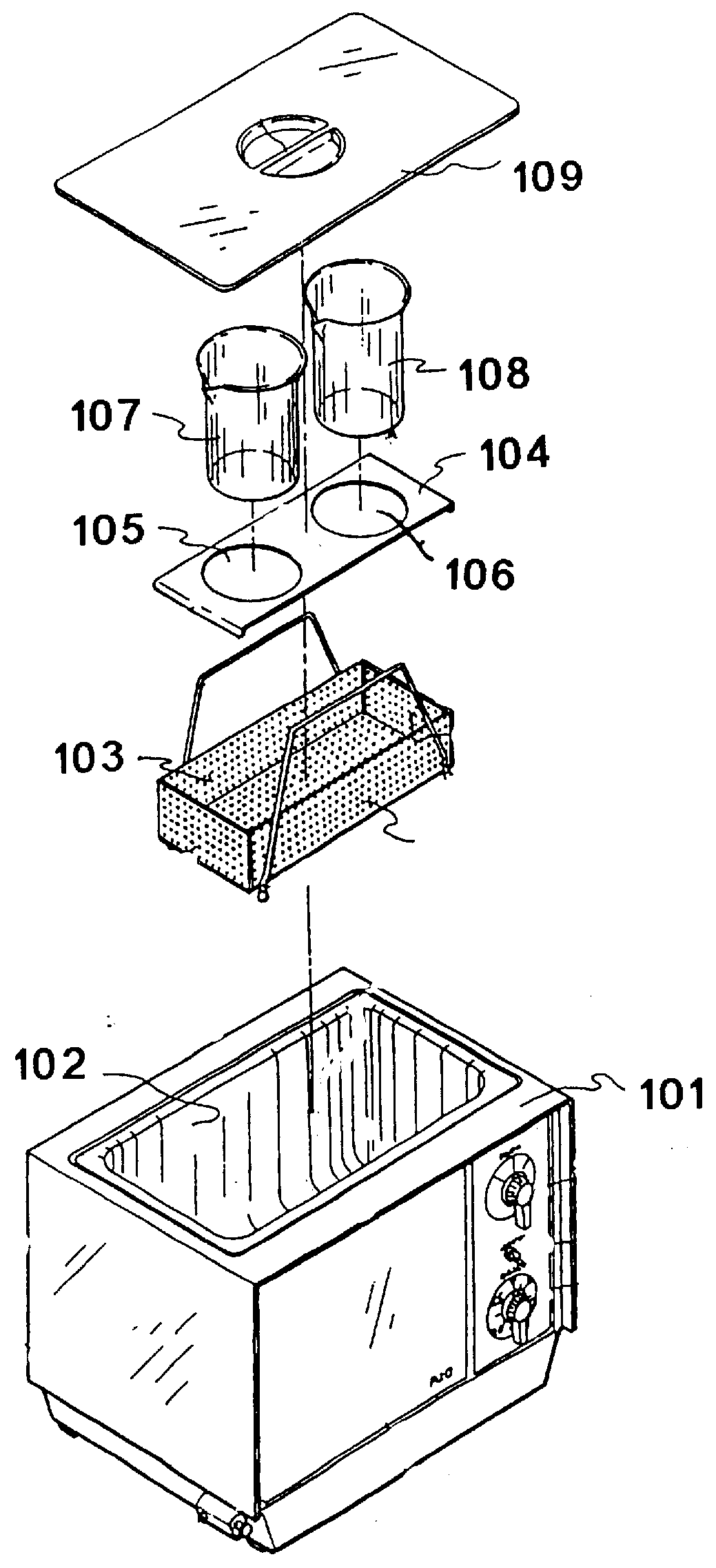
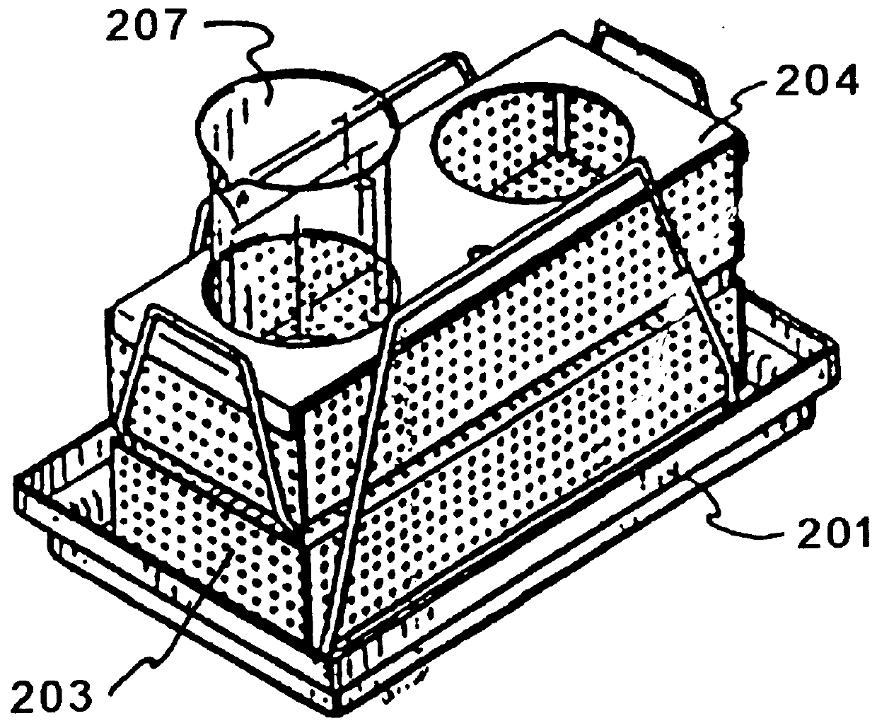
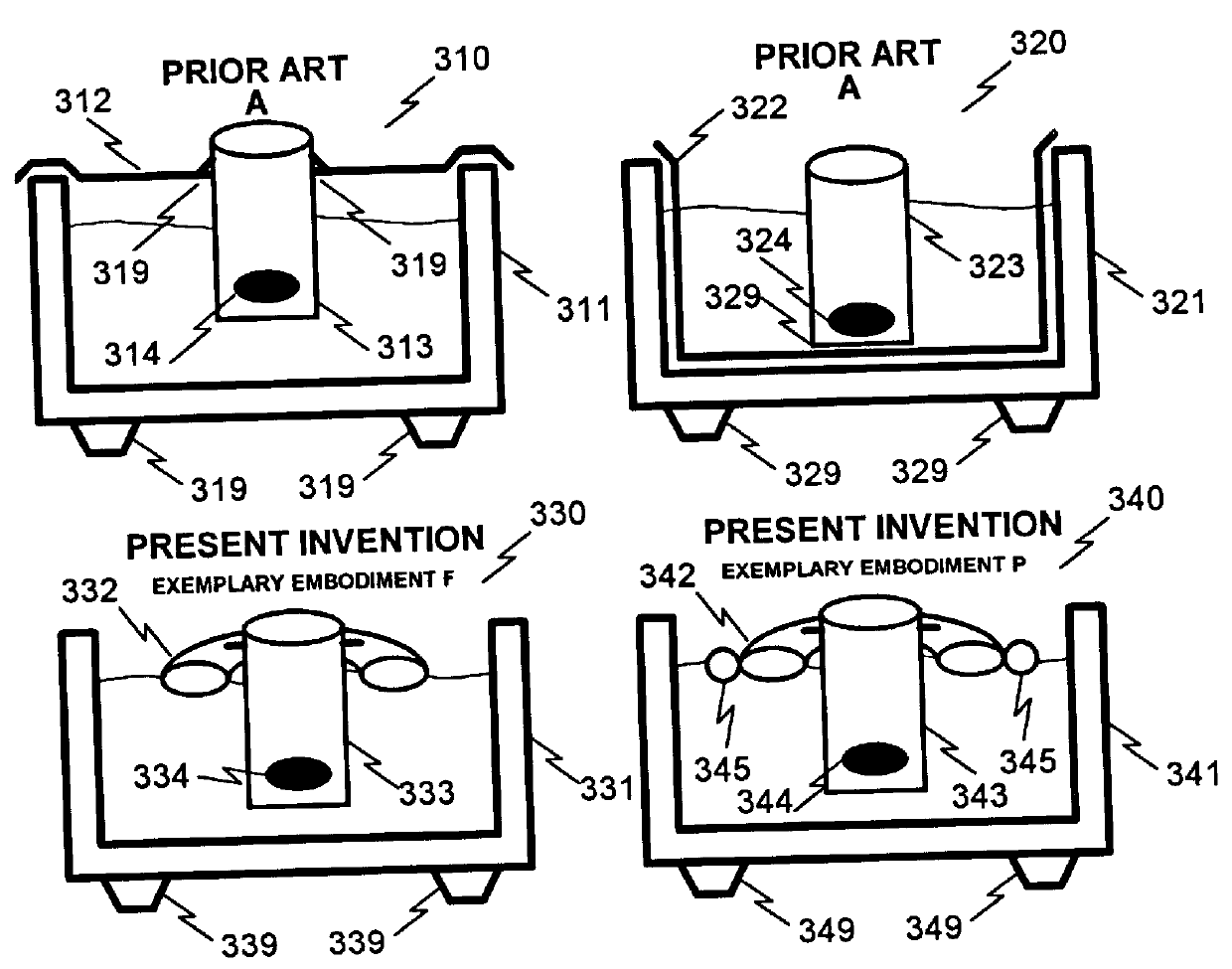
Referencing FIG. 3, the prior art ultrasonic cleaning means can be categorized into two typical systems: containment vessel cover lids (310) and beaker / basket systems (320).

Prior Art Containment Vessel Cover Lid Systems

Containment vessel cover lid systems (310) use a metallic lid to cover (312) to cover the ultrasonic bath (311), which supports a beaker or other containment vessel (313) that contains the cleaning target (314).

The major loss component associated with this configuration is the mechanical contact (319) which is ma...


PUM

PropertyMeasurementUnit
frequencyaaaaaaaaaa
temperaturesaaaaaaaaaa
ultrasonic wave energyaaaaaaaaaa

Abstract

A system and method of performing ultrasonic cleaning is disclosed whereby a conventional ultrasonic cleaning bath is augmented via the use of a cleaning target support structure and an optional mechanical isolator whereby the cleaning target is mechanically isolated from the ultrasonic cleaning bath. This isolation permits ultrasonic harmonics which are normally damped (suppressed) in amplitude due to conventional mechanical connections between the bath and the containment vessel to be fully applied to the cleaning target, resulting in substantial reduction in overall cleaning time and an improvement in cleaning efficiency. Various embodiments of the proposed system and method are disclosed, with several being preferred. Namely, the use of a circular floating-ballast to support a glass or plastic beaker used as the containment vessel is preferred as well as the use of a circular floating-ballast to support a plastic bag used as the containment vessel. Either of these configurations isolates the cleaning target from the sides of the ultrasonic bath. This isolation reduces the effective mass of the structure comprising the cleaning target, the containment vessel, and the containment vessel support (ballast means) and permits ultrasonic harmonics to fully affect cleaning with minimal harmonic damping. Consistent cleaning time improvements of 20-80% over conventional prior art basket-type and containment vessel support cover methods has been observed.

Description

PARTIAL WAIVER OF COPYRIGHTAll of the material in this patent application is subject to copyright protection under the copyright laws of the United States and of other countries. As of the first effective filing date of the present application, this material is protected as unpublished material.However, permission to copy this material is hereby granted to the extent that the copyright owner has no objection to the facsimile reproduction by anyone of the patent documentation or patent disclosure, as it appears in the United States Patent and Trademark Office patent file or records, but otherwise reserves all copyright rights whatsoever.Disclosure Document DepositsApplicant includes by reference and claims recorded date of conception by virtue of USPTO Disclosure Document Deposit Request FLOATING BEAKER POSITIONING DEVICE FOR ULTRASONIC CLEANING MACHINES, receipt 432155, mailed Jan. 12, 1998 to the USPTO with Express Mail Label EE046509055US and received by the USPTO Jan. 13, 1998.No...

Claims


Application Information

Patent Timeline
Patent Type & Authority Patents(United States)
IPC IPC(8): B08B3/12C23G3/00
CPCB08B3/12C23G3/00
Inventor RUSCZYK, LESTER LEE
Owner RUSCZYK LESTER LEE
Why Eureka
Try Eureka