Steered frequency phase locked loop

Inactive Publication Date: 2000-02-29
CURTAIN UNIV OF TECH
View PDF17 Cites 62 Cited by
  • Summary
  • Abstract
  • Description
  • Claims
  • Application Information

AI Technical Summary

Problems solved by technology

Most conventional PLLs have problems with false locking onto unwanted input signals, or unwanted spectral components of the input signal.
1. For the case where F.sub.c (s) doesn't contain a pole at the origin, the output frequency of the SFPLL tends to .omega.'.sub.r as the product of all the gains in the frequency loop K.sub.f1 tends to infinity, when the phase error .theta..sub..epsilon. (s)=0, for example when the input signal is zero.
2. For the case where F.sub.c (s) does contain a pole at the origin, the output frequency of the SFPLL equals .omega.'.sub.r when .theta..sub..epsilon.
3. If the SFPPL is to lock to a constant input frequency .omega.. Then a constant phase error between the input phase .theta..sub.i, and the output phase .theta..sub.o. is induced by the SFPLL. The magnitude of this phase error depends upon the difference between the input frequency .omega. and reference frequency .omega.'.sub.r. And also the ratio o

Method used


Image

  • Steered frequency phase locked loop
  • Steered frequency phase locked loop
  • Steered frequency phase locked loop

Examples


Embodiment Construction

2: Timing Recovery from NRZ Data

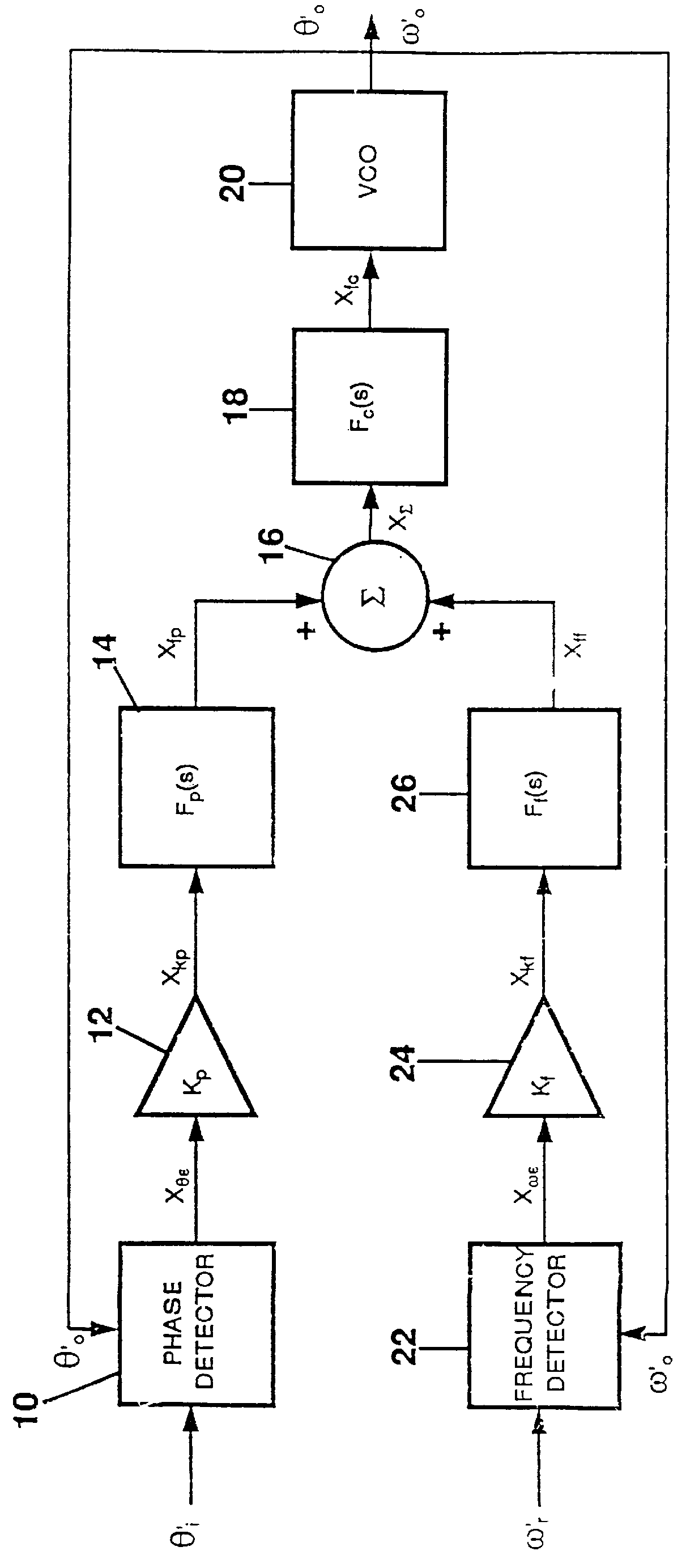
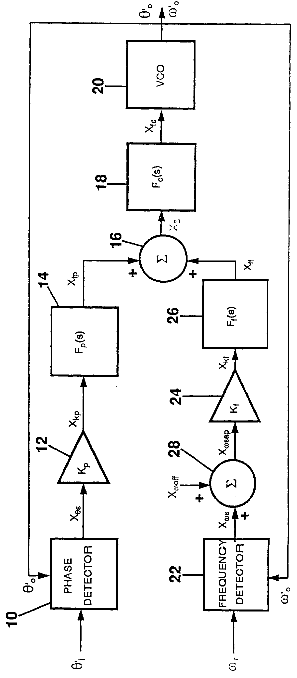
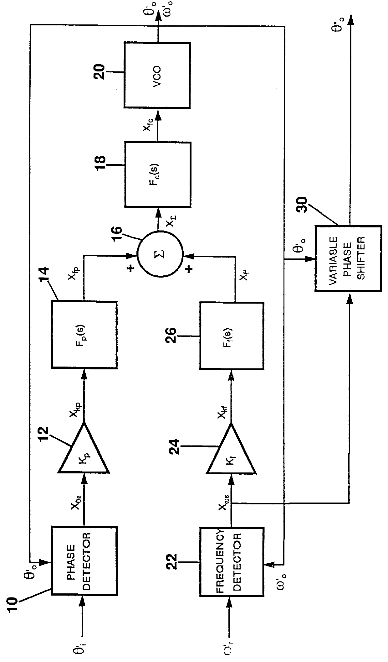
This section presents a system that employs the SFPLL technique to recover timing from a NRZ (NonReturn to Zero) data stream. Firstly the phase and frequency detector used in the SFPLL timing recovery system are described. A possible structure of the timing recovery system is presented in the System Overview section. Then in subsequent sections, timing recovery system components are examined, and parameters for the components are determined and related back to system requirements. The features and advantages of the SFPLL are discussed. Finally, full details of an actual implementation are given.

Phase and Frequency Detectors

This section describes the phase and frequency detectors used in the SFPLL timing recovery system. The particular phase and frequency detectors were chosen for their digital nature, allowing them to be easily realised with digital integrated circuit technology. Also, the digital nature of the frequency detector allows its output to ...


PUM


Abstract

PCT No. PCT/AU95/00793 Sec. 371 Date Sep. 30, 1997 Sec. 102(e) Date Sep. 30, 1997 PCT Filed Nov. 28, 1995 PCT Pub. No. WO96/17435 PCT Pub. Date Jun. 6, 1996A Steered Frequency Phase Lock Loop (SFPLL) comprises a phase loop that functions like a normal phase locked loop (PLL) and locks to the input signal, and a frequency loop that uses a reference frequency to influence the phase loop and effectively confines the output frequency of the phase loop and the SFPLL to be in a range of frequencies close to the reference frequency. The reference frequency is chosen to be very close to the input signal frequency that it is desired the SFPLL lock to. The SFPLL comprises a phase detector (10), a frequency detector (22), first and second gain components (12, 24), first, second and third filter components (14, 18, 26), a summer (16) and a voltage controlled oscillator (VCP)(20). By a judicious choice of the gains in the phase and frequency loops the SFPLL can be designed so that the range of frequencies to which the SFPLL will lock can be confined to an arbitrarily small region around the reference frequency ( omega 'r). Applications of the SFPLL include demodulation in CW modulation systems and timing recovery from NRZ data. Three advantages of the SFPLL are that the output frequency is equal or close to the reference frequency when no input signal is present, and the range of frequencies to which the SFPLL can lock is confined to a region around the reference frequency, and the phase and frequency instabilities of the VCO can be reduced.

Description

This invention relates to improvements in Phase Locked Loops (PLL) and relates particularly to a Steered Frequency Phase Locked Loop (SFPLL). The SFPLL is a system that exhibits PLL like behaviour but the range of frequencies to which it can lock is controlled. This invention has applications in many diverse areas of electronics, for example: timing recovery in base-band digital transmission, demodulation in continuous wave (CW) modulation systems, and filtering of electrical signals.BACKGROUND TO THE INVENTIONMost conventional PLLs have problems with false locking onto unwanted input signals, or unwanted spectral components of the input signal. The SFPLL avoids this false locking problem as the range of frequencies to which the SFPLL can lock can be confined to an arbitrarily small region around the desired input signal (providing of course the frequency of the input signal is known with sufficient accuracy). The SFPLL typically will not false lock providing there are no unwanted i...

Claims


Application Information

Patent Timeline
IPC IPC(8): H03L7/07H03L7/08H04L7/033H03L7/14
CPCH03L7/07H03L7/14H04L7/033H03L7/087
Inventor HILL, MARTIN
Owner CURTAIN UNIV OF TECH
Why Eureka
Try Eureka