Method for a surface treatment of metallic product

Inactive Publication Date: 2000-03-21
FUJI KIHAN CO LTD
View PDF16 Cites 44 Cited by
  • Summary
  • Abstract
  • Description
  • Claims
  • Application Information

AI Technical Summary

Problems solved by technology

Due to this, step management involving temperature control tends to be complicated and cost tends to increase accordingly.
The conventional surface treatment method, however, still has the following disadvantages to be further solved.
However, if the shot diameter is larger, the shot has disadvantageous in that the service life become shorter and in that the shot cracks more frequently.
Thus, it is clear that a larger shot tends to crack more easily and that its service life is, therefore, shorter.
If a shot easily cracks, manufacturing cost increases and stable injection is not ensured.
Further, the cracking shot causes a failure in a shot peening apparatus.
Besides, if the shot is larger, an impact applied on the apparatus itself increases, th

Method used


Image

  • Method for a surface treatment of metallic product
  • Method for a surface treatment of metallic product
  • Method for a surface treatment of metallic product

Examples


first embodiment

[First Embodiment]

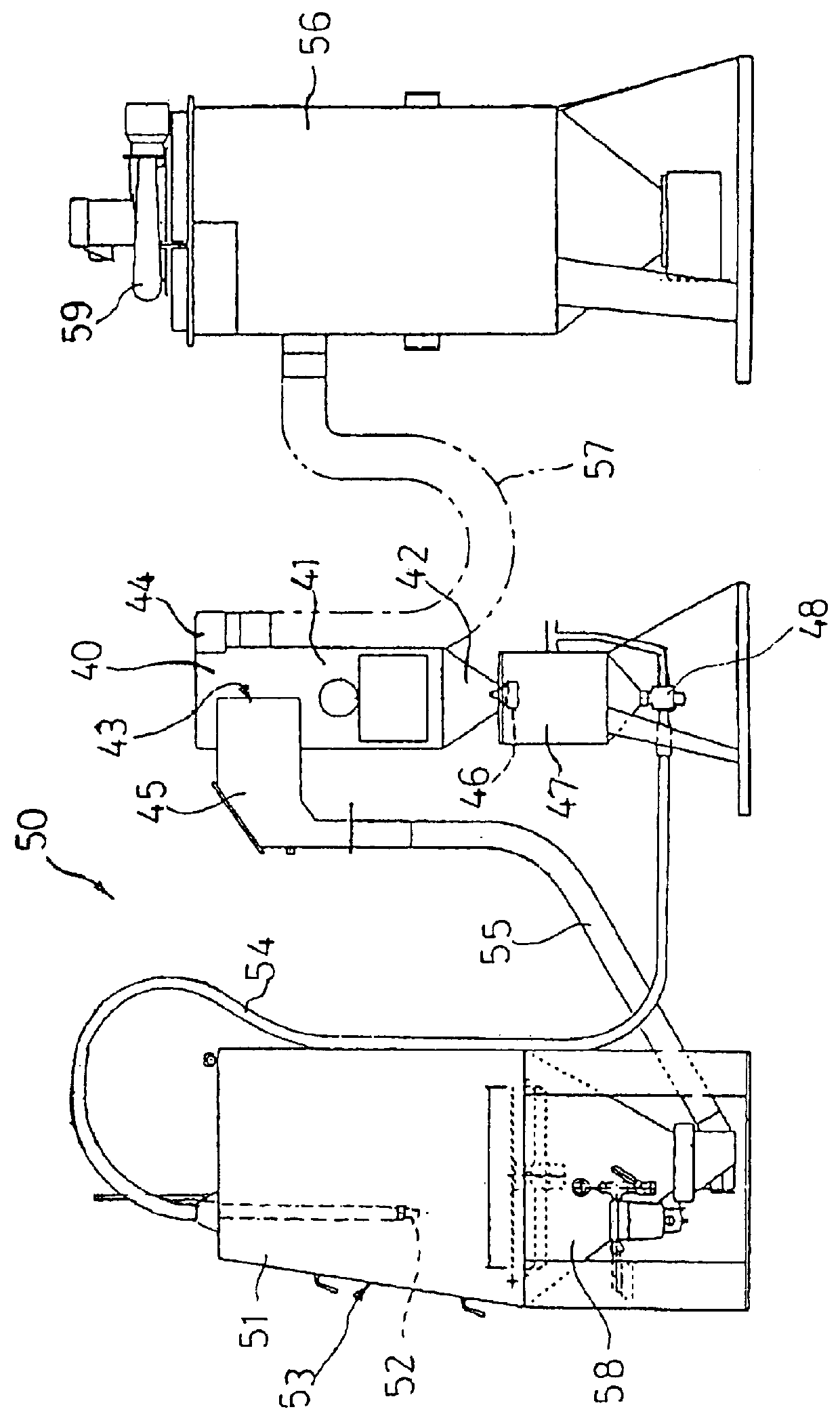
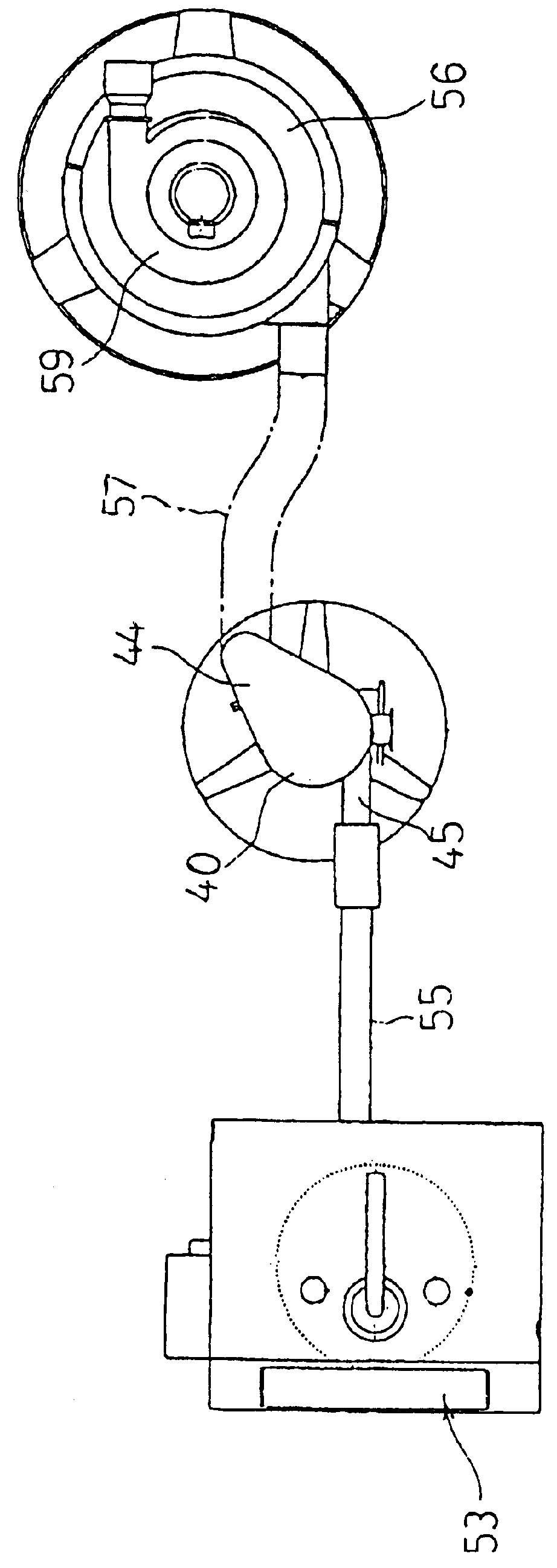
By using the above-described blasting apparatus 50, a gear (.phi. 100.times.20t, SCM420, carburized, quenched and tempered product) was housed into the cabinet 51 from the input port 53 as a product to be treated. Blasting was conducted by injecting mixed shots containing shots of different shot diameters onto the surface of the product to be treated.

The mixture shots, which consist of high-speed tool steel of shot diameters of 0.6 to 0.1 mm, were inputted into the recovery tank 40 and fell into the tank 47.

If compressed air was fed from a compressed air supply source, which is not shown, into the tank 47, the mixture shots were fed together with the compressed air by the shot quantity regulator 48 on the lower part of the tank 47 to the injection nozzle 52 of a diameter of 7 mm through the pipe 54. The mixture shots as well as the compressed air were injected from the injection nozzle 52 onto the product to be treated.

In a first comparison example, surface treatme...

second embodiment

In the second embodiment, a shaft (SCM420, carburized, quenched and tempered product, .phi. 30.times.300L) was used as a product to be treated and was subjected to surface treatment using mixture shots consisting of high-speed tool steel and having shot diameters of 0.4 to 0.05 mm as in the same manner as the first embodiment.

In the second comparison example, after shot peening was conducted using large shots of shot diameters of 0.7 to 0.5 mm, surface working and heat treatment, as described in the above-cited Japanese Patent No. 1594395, was conducted using shots of shot diameters of 0.1 mm.

The working conditions and results of the second embodiment and second comparison example are shown in Table 2 below.

third embodiment

In the third embodiment, a gear (SCM420, carburized, quenched and tempered product, .phi. 120.times.15t) was used as a product to be treated and was subjected to surface treatment using mixture shots consisting of high-speed tool steel and having shot diameters of 0.3 to 0.05 mm as in the same manner as the first embodiment.

In the third comparison example, after shot peening was conducted using large shots of shot diameters of 0.8 mm, CBN polishing was conducted.

The working conditions and results of the third embodiment and third comparison example are shown in Table 3 below.

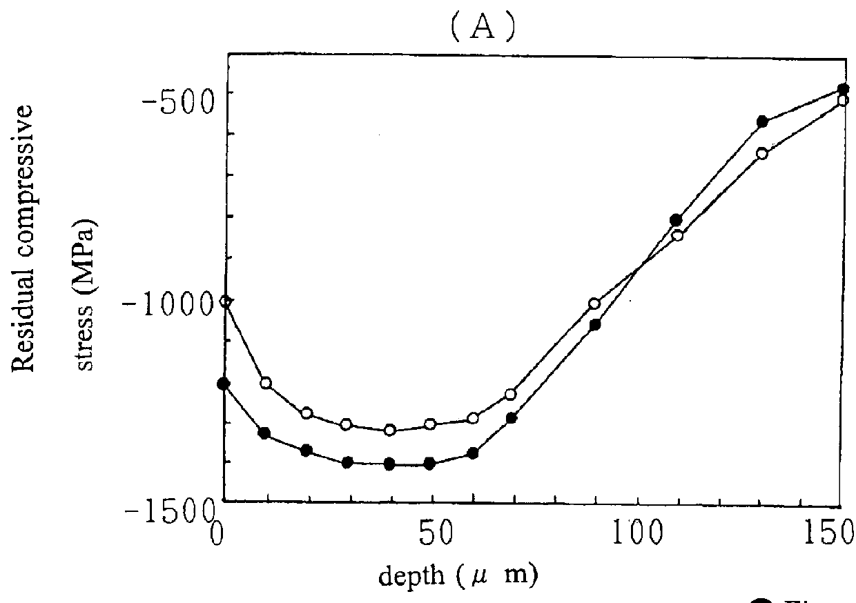
In the second and third embodiments, it was possible to obtain the peening effect and heat treatment effect with one blasting treatment. Also, since a residual compressive stress occurred below the surface of the product to be treated and the surface roughness was relieved, the surface hardness and fatigue strength of the product to be treated were enhanced.

In the third embodiment, in particular, compared with t...


PUM

PropertyMeasurementUnit
Lengthaaaaaaaaaa
Lengthaaaaaaaaaa
Pressureaaaaaaaaaa

Abstract

The present invention relates to a method for a surface treatment of a metallic product. In this method, by conducting one step of injecting mixture shots including at least two types of shots comprised of different or same materials consisting of high hardness metal or metallic component and having different shot diameters between 0.6 and 0.03 mm onto the surface of a metallic product at an injection pressure of not less than 0.29 MPa or not less than 50 m/sec, the residual compressive stress of the surface of the metallic product and that of a lower surface layer are made at least -1200 MPa and that of a portion having a depth of about 50 mu m below the surface of the metallic product is made -1300 MPa or higher.

Description

1. Field of the InventionThe present invention relates to a surface treatment of a metallic product such as a tool and a machine part, and particularly relates to a method for a surface treatment including a single step aimed to harden the surface of a metallic product and to increase fatigue strength thereof by heat treatment and hardening and by generating a residual compressive stress on the surface thereof and to exhibit advantages of enhancing the quality of the surface by heat treatment, of enhancing the residual compressive stress deeper inside the surface thereof and of relieving the surface roughness, without the need to conduct many shot peening steps or a treatment step, such as a polishing step, after a peening step.2. Description of the Related ArtConventionally, there has been known, as a method for a surface treatment of a metallic product, shot peening by which all of or part of a metallic product, such as a cast steel product, a casting product and a stainless steel...

Claims


Application Information

Patent Timeline
IPC IPC(8): C21D7/06C21D7/00B24C11/00B24C1/10
CPCC21D7/06Y10T29/479
Inventor MIYASAKA, YOSHIO
Owner FUJI KIHAN CO LTD
Why Eureka
Try Eureka