Ground heat exchange system

a heat exchange system and ground technology, applied in the direction of heat pumps, insulation, borehole/well accessories, etc., can solve the problems of requiring as much time for the manifolding and trenching of the surface pipe, and achieve the effect of reducing the space required, reducing the amount of trenching, and maintaining a clean, dry drill si

Inactive Publication Date: 2000-03-28
ENLINK GEOENERGY SERVICES
View PDF55 Cites 43 Cited by
  • Summary
  • Abstract
  • Description
  • Claims
  • Application Information

AI Technical Summary

Benefits of technology

In one system and method according to the present invention a coiled tubing unit (CTU) is used to drill heat loop bore holes. The CTU has a reel on which is wrapped continuous flexible steel tubing, an injector which transports the tubing into and out of the hole, a drill bit on the end of a down hole motor, and a pump which supplies fluid for drilling. The motor is rotated by the pump pressure from the surface, which allows the unit to drill without rotating the drill string. This feature results in several benefits not possible with conventional drilling rigs. Directional drilling allows multiple wells to be drilled from one location. It also reduces the space required between bore holes and allows them to be drilled in a very close proximity to the subject building. This process not only reduces 80 percent of trenching on some jobs, but allows the unit to drill under existing slabs, driveways, parking lots and buildings. The compact design and directional drilling capabilities opens the retrofit market to geothermal systems.
With a method according to the present invention a relatively short surface trench is excavated before drilling is started. The drilling machine straddles the trench, drilling bore holes in the bottom of the trench as it moves over the length of the trench. A solids control system which cleans the drilling fluid as it is pumped from the hole, allowing cuttings to be dry discharged in a designated area, thereby maintaining a clean, dry drill site. As each hole is drilled, a track mounted rig moves approximately two to three feet down the trench to the next drilling location. A grout reel is then positioned over the previously drilled hole. This reel has a flexible grout pipe wrapped around a powered reel. As the grout pipe is pushed down the bore hole, it takes a plastic heat loop with it to the bottom of the hole. In certain preferred embodiments the loop is secured in the hole with an anchor apparatus; then the grout pipe is retracted while filling the hole with grout. Since a sinker bar is not required in this process, a 3 to 31 / 4 inch diameter hole is drilled, in certain embodiments, compared to a conventional 4 to 41 / 2 inch hole. This results in faster penetration, improved fuel efficiency, and improved heat transfer to the earth.

Problems solved by technology

The trenching and manifolding of the surface pipe typically takes as much time as the wellbore drilling and pipe installation.

Method used


Image

  • Ground heat exchange system
  • Ground heat exchange system
  • Ground heat exchange system

Examples


Embodiment Construction

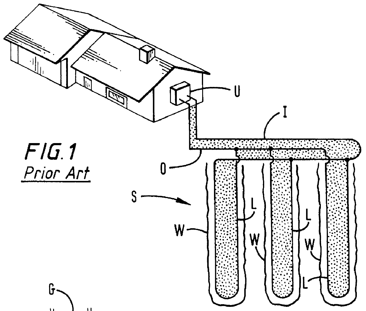
Referring now to FIG. 1, a prior art underground heat exchange pipe loop system S has a plurality of wellbores W, each e.g. about 250 feet deep and 4 to 4.5 inches in diameter, which are preferably, between about ten feet to fifteen feet apart. Water flows from a building's processing unit U in an inlet pipe I into each inlet side of a plurality of pipe heat exchange loops L and then flows up in each outlet side of the loops L to an outlet pipe O which is in fluid communication with the processing unit U. Pipes I and O are typically about 45 feet long for a three loop system as shown (preferably about ten to fifteen feet between each loop).

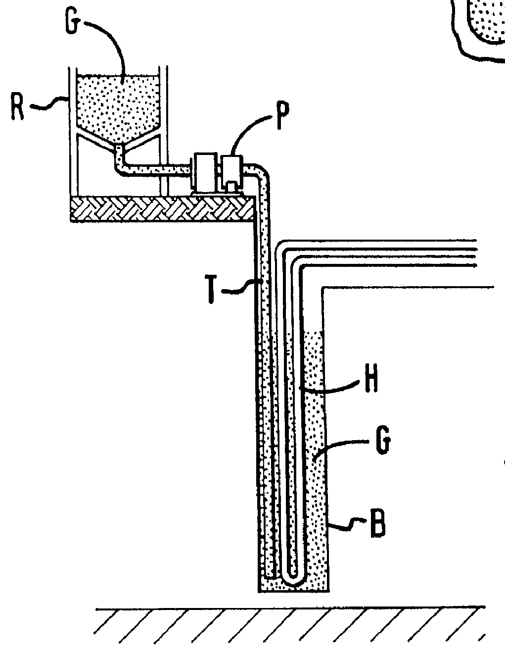
FIG. 2 illustrates a prior art system and method for grouting a wellbore such as the wellbores W in FIG. 1. After a pipe heat exchange loop H is installed in a wellbore B, a grout pipe T is inserted into the wellbore B. A grout pump P then pumps grout G from a reservoir R down the grout pipe T from which it flows into the wellbore B.
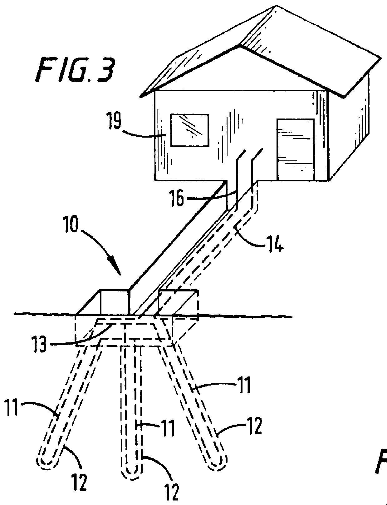
FIG. 3 shows a...


PUM


Abstract

A system and method for simultaneously installing a pipe loop and a grout pipe in a wellbore has been invented which, in one aspect, is used to grout the wellbore by releasing the grout pipe from the pipe loop or from a bottom member connected with the pipe loop and then introducing grout through the pipe into the wellbore as the grout pipe is removed upwardly from the wellbore. In one aspect the system has a curved member or members or a ball or part thereof at the bottom of the pipes to facilitate movement of the system through a wellbore.

Description

1. Field of the InventionThe present invention is directed to underground heat exchange systems and to apparatus and methods for installing a loop of pipe in a hole in the earth.2. Description of Related ArtThe prior art discloses a variety of systems and apparatuses for installing ground heat exchange pipe loops in a wellbore, including a system in which a wellbore is drilled, e.g. a vertical hole four to four-and-a half inches in diameter to a depth of about 250 feet, and a single piece of polyethylene pipe attached to a sinker bar is introduced into the hole and then pulled out of the hole manually while grout is introduced into the hole. A pipe loop (polyethyelene) is pushed to the bottom of the hole by a wire-line retrievable sinker bar. With the sinker bar removed, a series of screwed together 2 inch PVC tremmie pipes is lowered to the bottom of the hole and "grout," (bentonite clay mixture) batch mixed at the surface is pumped into the tremmie pipe. As each batch is pumped in...

Claims


Application Information

Patent Timeline
Patent Type & Authority Patents(United States)
IPC IPC(8): E21B33/13E21B23/00F28F27/00F25B30/06F25B30/00F28D20/00
CPCE21B23/00E21B33/13F24J3/083F25B30/06F28D20/0052F28F27/00Y02E10/125Y02E60/142F24T10/15Y02E10/10Y02E60/14
Inventor AMERMAN, THOMAS R.
Owner ENLINK GEOENERGY SERVICES
Why Eureka
Try Eureka