Method for producing ceramic diaphragm structure

a diaphragm and ceramic technology, applied in the direction of generators/motors, layered products, basic electric elements, etc., can solve the problems of large waviness of the diaphragm structure, warpage, and difficulty in reforming the aforementioned warpage and waviness

Inactive Publication Date: 2000-04-04
NGK INSULATORS LTD
View PDF8 Cites 22 Cited by
  • Summary
  • Abstract
  • Description
  • Claims
  • Application Information

AI Technical Summary

Benefits of technology

Accordingly, the present invention aims to provide a method for producing a ceramic diaphragm structure, which can form a diaphragm portion having a protrusion toward the side opposite to a window portion of a substrate and which can advantageously minimize a waviness of a diaphragm structure and / or a warpage of a ceramic plate including diaphragm structures.

Problems solved by technology

In this method, a diaphragm structure has a large waviness, and a warpage is caused wholly in a ceramic plate including diaphragm structures.
It is difficult to reform the aforementioned warpage and waviness even if the ceramic plate 15 is subjected to firing again with loading.

Method used


Image

  • Method for producing ceramic diaphragm structure
  • Method for producing ceramic diaphragm structure
  • Method for producing ceramic diaphragm structure

Examples


example 1

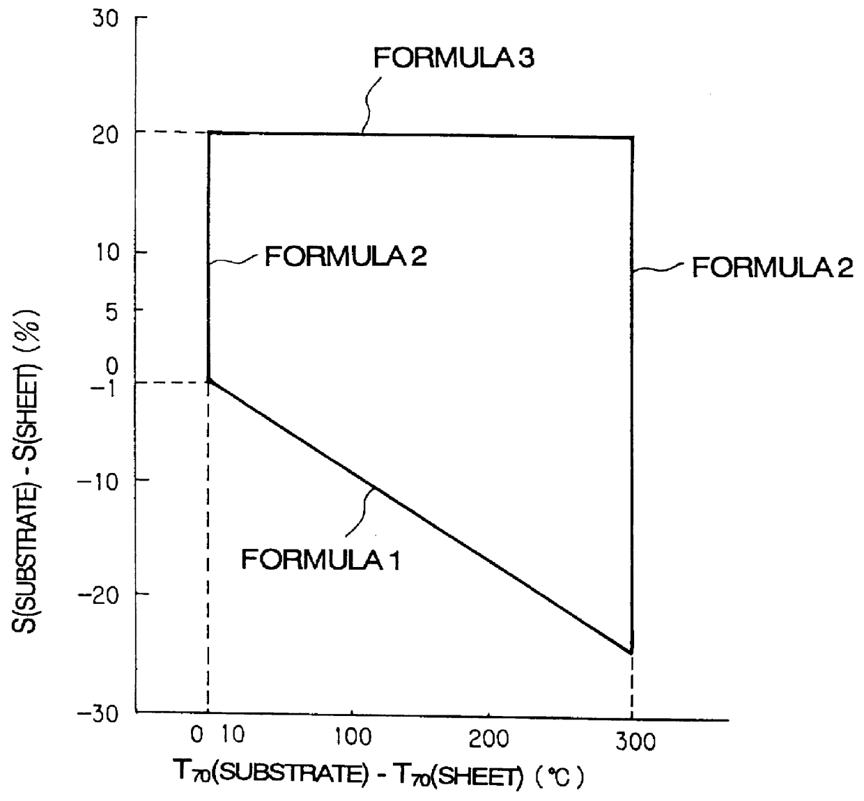
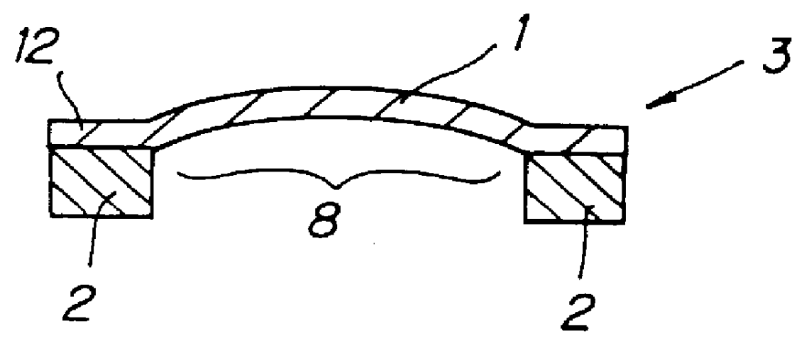
By a method of the present invention, there is produced a ceramic diaphragm structure having a substrate having two layers so as to satisfy the aforementioned formulae 1), 2), 3), and 4).

To 100 parts by weight of a partially stabilized zirconia powder (containing 0.1-0.5% of alumina) having an average particle diameter of 0.4-1.0 .mu.m were added 7.6 parts by weight of poly(vinyl butyral) as a binder, 3.8 parts by weight of dioctyl phthalate as a plasticizer, 80 parts by weight of mixture of toluene and 2-propanol in the ratio of 1:1 (by volume) as a solvent, and 0-2.0 parts by weight of sorbitan fatty acid ester as a dispersant as necessary. They were mixed together by a ball mill for 5-50 hours so as to obtain a slurry. The slurry was deaired and a viscosity was adjusted so that the slurry for the green sheet has a viscosity of 2000 cps and that the slurry for the green substrate has a viscosity of 20000 cps.

The aforementioned slurry was molded so as to have a predetermined shape ...

examples 2-8

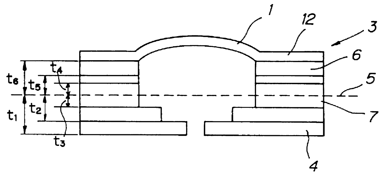
In each of Examples 2-8, a ceramic plate having four ceramic diaphragm structures which satisfies the aforementioned formulae 1), 2), 3), and at least one of the formulae 4) and 5) and which consists of two layers was produced in the same manner as in Example 1 except that a mid-sintering temperature and a shrinkage rate of each of the layers constituting a green substrate were changed. In each of Examples 4 and 8, a mid-sintering temperature and a shrinkage rate of a green sheet were 1262.degree. C. and 21.38%, respectively.

The aforementioned diaphragm structures were measured for a protrudent shape of a diaphragm portion, a waviness of the diaphragm structures and / or a warpage of a ceramic plate including the diaphragm structures. The results are shown in Table 1. In Table 1 are also shown values such as a difference in average sintering temperature of a green substrate, the values being calculated on the basis of a mid-sintering temperature and a shrinkage rate of each of layers ...

example 9

A ceramic plate having diaphragm structures which substrate consists of five layers was produced so as to satisfy the formulae 1), 2), 3), 4), and 5).

With 100 weight parts of an alumina powder having an average diameter ranging from 0.2 to 0.8 .mu.m were mixed 11 weight parts of poly(vinyl butyral) resin as a binder, 5.5 weight parts of dioctyl phthalate as a plasticizer, 11 weight parts of a mixture of toluene and 2-propanol in the ratio of 1:1 by volume as a solvent, and 0-3.0 weight parts of sorbitan fatty acid ester as a dispersant as necessary by a ball mill for 5-50 hours so as to prepare a slurry. The slurry was deaired, and viscosity of the slurry was adjusted to be 2000 cps for a green sheet and 20000 cps for a green substrate. Each of the layers constituting a green substrate and a green sheet was formed in the same manner as in Example 1.

By controlling the same factor as Example 1, a shrinkage rate and a mid-sintering temperature of the green sheet were adjusted to be 21....


PUM

PropertyMeasurementUnit
shrinkage rateaaaaaaaaaa
thicknessaaaaaaaaaa
thicknessaaaaaaaaaa

Abstract

A method for producing a ceramic diaphragm structure includes preparing a ceramic green substrate having at least one window and a plurality of layers, and a thin ceramic green sheet. The ceramic green sheet is superposed on the ceramic green substrate to cover the window and thereby provide a unitary laminate. The laminate is then fired so that the ceramic green sheet provides a diaphragm portion which protrudes in a direction away from the window. The average sintering temperature difference or the average shrinkage-rate difference, of the layers of the ceramic green substrate, is larger than zero.

Description

BACKGROUND OF THE INVENTION AND RELATED ART STATEMENTThe present invention relates to a method for producing a ceramic diaphragm structure which is used as a constitutional member in various kinds of sensors, piezoelectric / electrostrictive actuators, or the like.A ceramic diaphragm structure has a structure in which a thin and flexible diaphragm plate is superposed on a substrate having at least one window portion so as to cover the window portion and to work as a diaphragm. Such a ceramic diaphragm structure is used for various kinds of sensors by constituting so that a diaphragm portion detects a bending displacement originated from a subject to be measured by an adequate means, or used as a constituting member of a piezoelectric / electrostrictive actuator by giving a pressure to the pressure room formed inside the actuator by deformation of the diaphragm portion.A ceramic diaphragm structure is produced by unitarily superposing a thin ceramic green sheet (hereinafter referred to a...

Claims


Application Information

Patent Timeline
Patent Type & Authority Patents(United States)
IPC IPC(8): C04B35/111C04B35/486H01L41/09
CPCC04B35/111H01L41/098C04B35/486H10N30/2048
Inventor TAKEUCHI, YUKIHISANANATAKI, TSUTOMUTAKEUCHI, KATSUYUKI
Owner NGK INSULATORS LTD
Why Eureka
Try Eureka