Vehicle safety device

a safety device and vehicle technology, applied in the field of vehicle safety devices, can solve the problems of not memorising conditions, unable to act as a black box in the event of an accident, and unable to diagnose, with accuracy, and large increase in current passing in the initiator

Inactive Publication Date: 2000-04-18
BICKFORD DAVEY
View PDF16 Cites 40 Cited by
  • Summary
  • Abstract
  • Description
  • Claims
  • Application Information

AI Technical Summary

Benefits of technology

In particular, the aim of the invention is a safety device with a modular architecture, making it possible to modify its elements simply.
The invention also has the aim of being able to integrate pyrotechnic initiators built around semi-conducting bridges, whilst periodically checking their working condition in a simple way and with high reliability.
Another object of the invention is to be able to sequence precisely the successive triggering of several safety systems.
This configuration permits great flexibility of design and of use. One and the same safety device can then be the subject of particular programming in order to be integrated into vehicles that are differently equipped. Isolated operations on certain elements are particularly simple. Moreover, it is easy to expand the contents of the device.
In an advantageous way, the device according to the invention comprises a pulse micro-generator that allows the generation in the circuit of electrical pulses precisely calibrated in time and in amplitude. These pulses allow verification of the functionality of the pyrotechnic initiators.

Problems solved by technology

In this way, the initiator has a small current passing through it that is insufficient to cause it to be triggered.
When a collision or a large deceleration of the vehicle is detected, one or more sensors are closed successively, causing a large increase in the current passing in the initiator.
A major disadvantage of these safety devices is that they are designed to collect information solely from acceleration sensors.
Another disadvantage of these devices is that they do not memorise information relating to the conditions of the progress of a journey.
They cannot therefore act as a black box in the event of an accident, nor diagnose, with accuracy the source of a breakdown.
Furthermore, these devices impose the simultaneous triggering of the whole of the safety systems provided in a vehicle.
This method, usable for resistive elements, is not suitable in the presence of semi-conducting elements.
It is therefore not possible to integrate pyrotechnic initiators built around semiconducting bridges.
Another disadvantage appears when there is a fault in one of the sensors linked to an initiator.
In this way, if a passenger remains safe from a premature or untimely triggering of the safety systems, his safety is no longer guaranteed in the event of a crash.
It is therefore difficult to integrate them into different vehicles corresponding to distinctive measurement means and safety mechanisms.
Another disadvantage is apparent in the presence of one or several initiators built around semi-conducting bridges.
This indirect method has proved to be both rather impractical and only moderately reliable.

Method used


Image

  • Vehicle safety device

Examples


Embodiment Construction

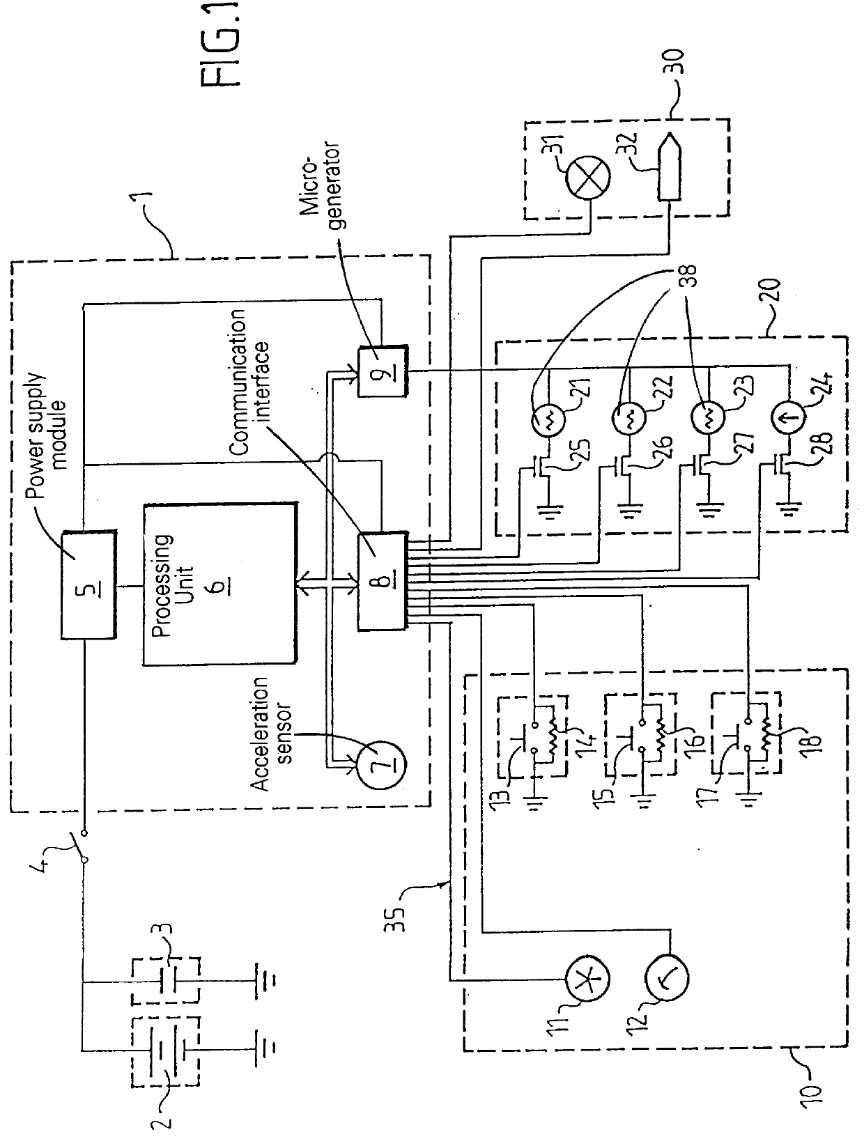
In the embodiment described, the safety device according to the invention comprises an energy source 2 supplying circuit wiring 35 extending into the whole of the device. The energy source 2 is typically a battery of an automobile. It is connected, in parallel, with an energy reservoir 3 intended to remedy a failure of this battery 2 in the event of a crash.

The safety device also comprises a management module 1 permitting analysis of information on the conditions of a journey and commanding the safety mechanisms. The energy source 2 is separated from the management module 1 by a contact switch 4, which allows the device to be switched on and off. The management module 1 is preferably included in an integrated circuit.

The management module 1 is made up of a power supply module 5, a processing unit 6, a pulse micro-generator 9, an integrated acceleration sensor 7 and a communication interface 8.

The power supply module 5 is intended to supply a continuous voltage to the rest of the dev...


PUM


Abstract

PCT No. PCT / FR96 / 00491 Sec. 371 Date Jan. 2, 1997 Sec. 102(e) Date Jan. 2, 1997 PCT Filed Apr. 1, 1996 PCT Pub. No. WO96 / 30231 PCT Pub. Date Oct. 3, 1996A safety device for a vehicle includes detection systems, safety mechanisms and safety systems, at least certain of the safety systems including pyrotechnic initiators. When certain of the detection systems detect a danger for a passenger, they trigger safety systems which activate the mechanisms. The safety device also may include a processing unit connected to the detection and safety systems by a communication interface; the processing unit analyses information signals coming from the detection systems and generates command signals directed to the safety systems.

Description

This invention relates to a safety device applicable to a vehicle, and more particularly to an automobile.DESCRIPTION OF THE RELATED ARTPyrotechnic safety devices used in automobiles usually consist of safety circuits made up of an electrical power source supplying a certain voltage to the terminals of a pyrotechnic initiator connected, in series, with one or several acceleration sensors. The initiator having a fixed internal resistance, the sensors are generally shunted by a resistance having a nominal value greater than that of the internal resistance of the initiator. In this way, the initiator has a small current passing through it that is insufficient to cause it to be triggered. When a collision or a large deceleration of the vehicle is detected, one or more sensors are closed successively, causing a large increase in the current passing in the initiator.The mechanism is then ignited, activating a mechanism which is linked to it. Typically the mechanism is a safety air bag.A m...

Claims


Application Information

Patent Timeline
Patent Type & Authority Patents(United States)
IPC IPC(8): B60K28/14B60K28/10B60R21/01E05B51/02E05B65/12E05B51/00B60R22/46B60J5/00B60R21/16
CPCB60K28/14E05B77/12E05B51/023B60R21/01
Inventor PATHE, CLAUDETROUSSELLE, RAPHAEL
Owner BICKFORD DAVEY
Why Eureka
Try Eureka