Heating element, manufacturing process and application

a heating element and manufacturing process technology, applied in the field of new electrical heating elements, can solve the problems of large implements, inability to adapt to complex contours, and inertia of thermal inertia

Inactive Publication Date: 2000-04-25
SAINT GOBAIN PERFORMANCE PLASTICS CORP
View PDF10 Cites 70 Cited by
  • Summary
  • Abstract
  • Description
  • Claims
  • Application Information

AI Technical Summary

Problems solved by technology

One drawback of this type of electrical heating element is its thermal inertia.
Another drawback is that it is ill-suited to complex contours.
Furthermore, it is thick and the implements which use it are large.
One drawback of this heating element is the low conducti

Method used


Image

  • Heating element, manufacturing process and application
  • Heating element, manufacturing process and application
  • Heating element, manufacturing process and application

Examples


Embodiment Construction

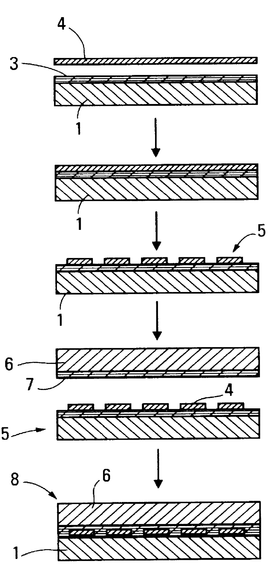
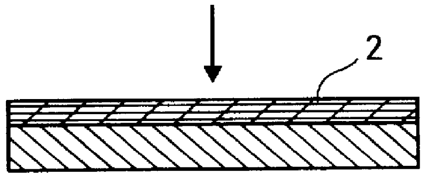
FIG. 1, the substrate 1 used as a support is a sheet formed from an 80 .mu.m thick PTFE-impregnated glass fabric. A layer 2 of PFA in dispersion in water is deposited on this substrate by the technique of coating using a scraper or a pencil.

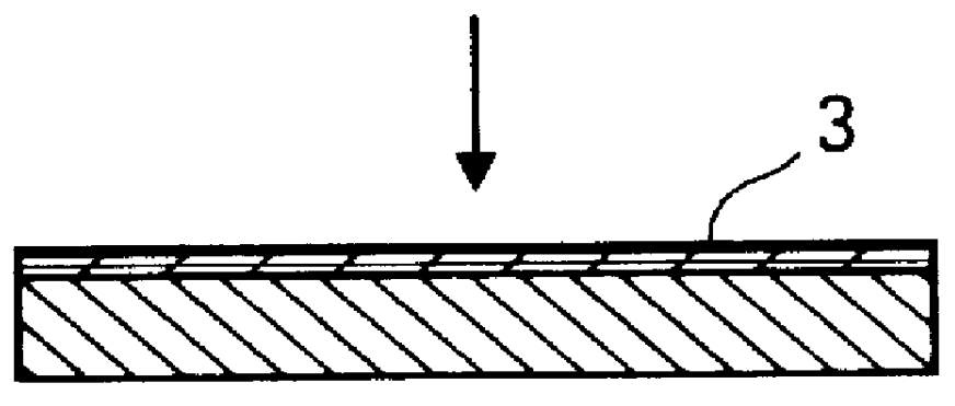
After drying at a temperature of 350.degree. C., an approximately 10 .mu.m thick layer is obtained.

A 50 .mu.m thick Constantan.RTM. metal sheet 4 is deposited on this layer 3, and these elements are assembled by pressing between the plates of a press, under a pressure of 40 bar at 350.degree. C. for a few minutes.

After having protected the parts of the metal sheet which are intended to form the electrical resistor using a varnish deposited by screen printing, the assembly is treated with a mixture of hydrochloric acid and hydrogen peroxide in order to obtain the desired shape for the heating resistor through chemical etching. A prelaminated element 5 is obtained. A second substrate 6, coated with a layer of binder 7 and obtained, as in the case o...


PUM


Abstract

PCT No. PCT/IB96/00390 Sec. 371 Date Feb. 19, 1998 Sec. 102(e) Date Feb. 19, 1998 PCT Filed Apr. 30, 1996 PCT Pub. No. WO96/35317 PCT Pub. Date Nov. 7, 1996A heating element includes at least one substrate, at least one electrical resistance layer, and a binder configured to bind the electrical resistance layer to the substrate, wherein the binder has a melting temperature greater than an operating temperature of the heating element and includes a perfluorinated polymer.

Description

1. Field of the InventionThe present invention relates to a novel electrical heating element in the form of a film or thin sheet with laminated structure, comprising at least one electrically conductive layer and at least one substrate.2. Discussion of the BackgroundElectrical heating elements used in household applications, for example, irons, grills, etc. are formed by resistance wires embedded in an insulating ceramic material, itself placed in a metal casing. One drawback of this type of electrical heating element is its thermal inertia. Another drawback is that it is ill-suited to complex contours.Furthermore, it is thick and the implements which use it are large.Electrical heating elements are also known which are in the form of sheets having multiple layers; an electrically conductive layer formed by a thin metal film, bonded onto a substrate by means of a hot-melt adhesive layer which is intended to withstand heat. Suitable hot-melt layers are extruded films having a thickne...

Claims


Application Information

Patent Timeline
IPC IPC(8): D06F75/24D06F75/26D06F75/08H05B3/22H05B3/28H05B3/20
CPCD06F75/24D06F75/26H05B3/283H05B3/286H05B3/28H05B2203/003
Inventor PETIT, DOMINIQUEWOLKI, PETER
Owner SAINT GOBAIN PERFORMANCE PLASTICS CORP
Why Eureka
Try Eureka