Method and apparatus for synchronized clock distribution

a clock signal and circuit technology, applied in the direction of generating/distributing signals, instruments, pulse techniques, etc., can solve the problems of inability to synchronize circuits, different propagation delays of received clock signals, and out of phase with each other

Inactive Publication Date: 2000-05-02
GOOGLE LLC
View PDF7 Cites 28 Cited by
  • Summary
  • Abstract
  • Description
  • Claims
  • Application Information

AI Technical Summary

Problems solved by technology

Serious problems can result if the clock signals received by different parts of the circuit are not synchronized.
A lack of synchronization can occur because because the different parts of the circuit are at different distances from the clock source.
This causes the received clock signals to have different propagation delays and to be out of phase with each other.
This problem, known as clock skew, can occur at the system level, the board level, and the chip level, and it becomes more severe as the circuit size increases and as the clock speed increases.
However, the speed of distributing a clock signal is limited by the speed of light in the medium.
These limitations limit the potential benefits of this solution.
In practice, however, this solution creates problems of synchronizing the various clocks.
Additionally, each additional clock takes up valuable space on the chip.

Method used


Image

  • Method and apparatus for synchronized clock distribution
  • Method and apparatus for synchronized clock distribution
  • Method and apparatus for synchronized clock distribution

Examples


Embodiment Construction

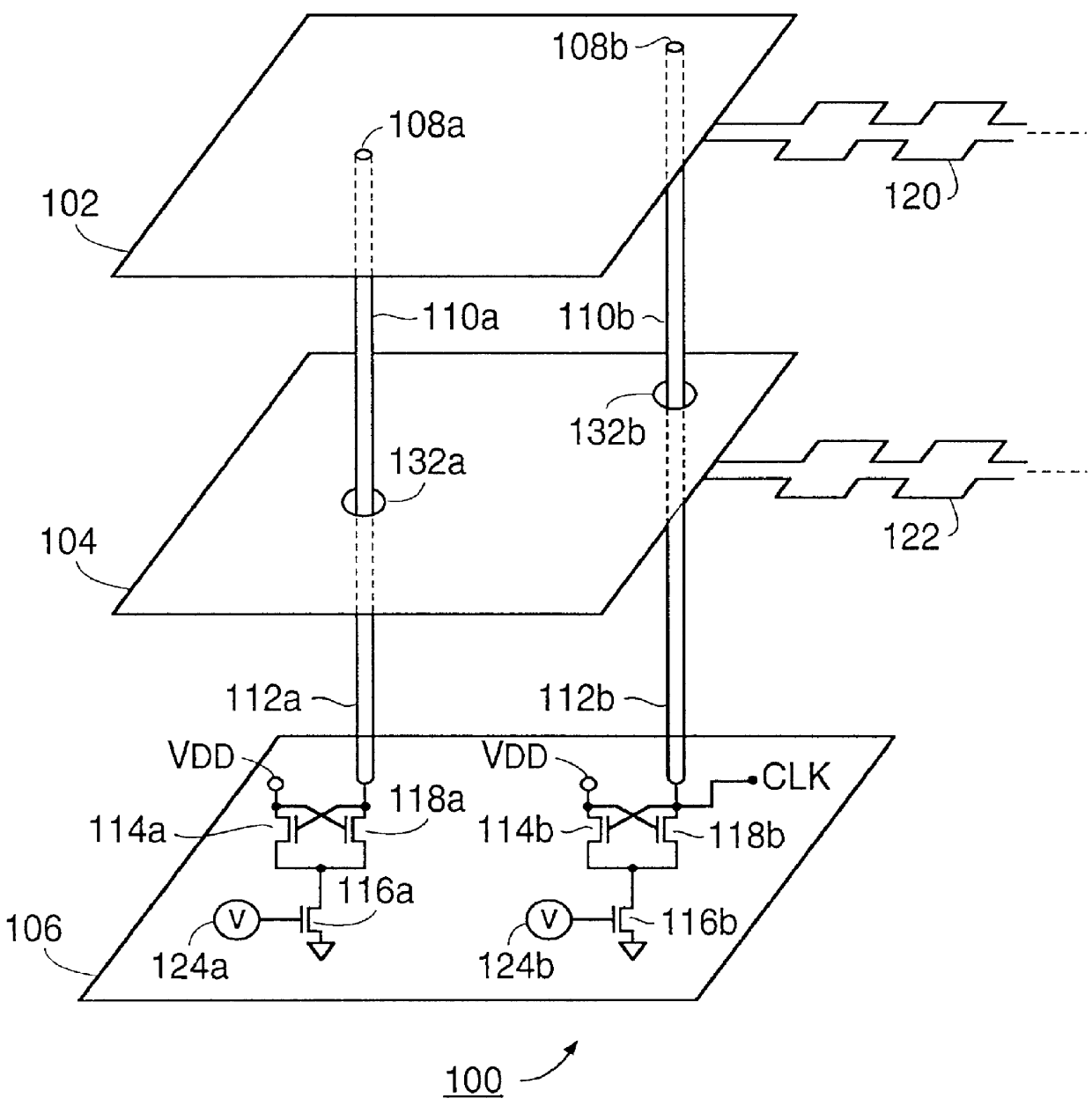
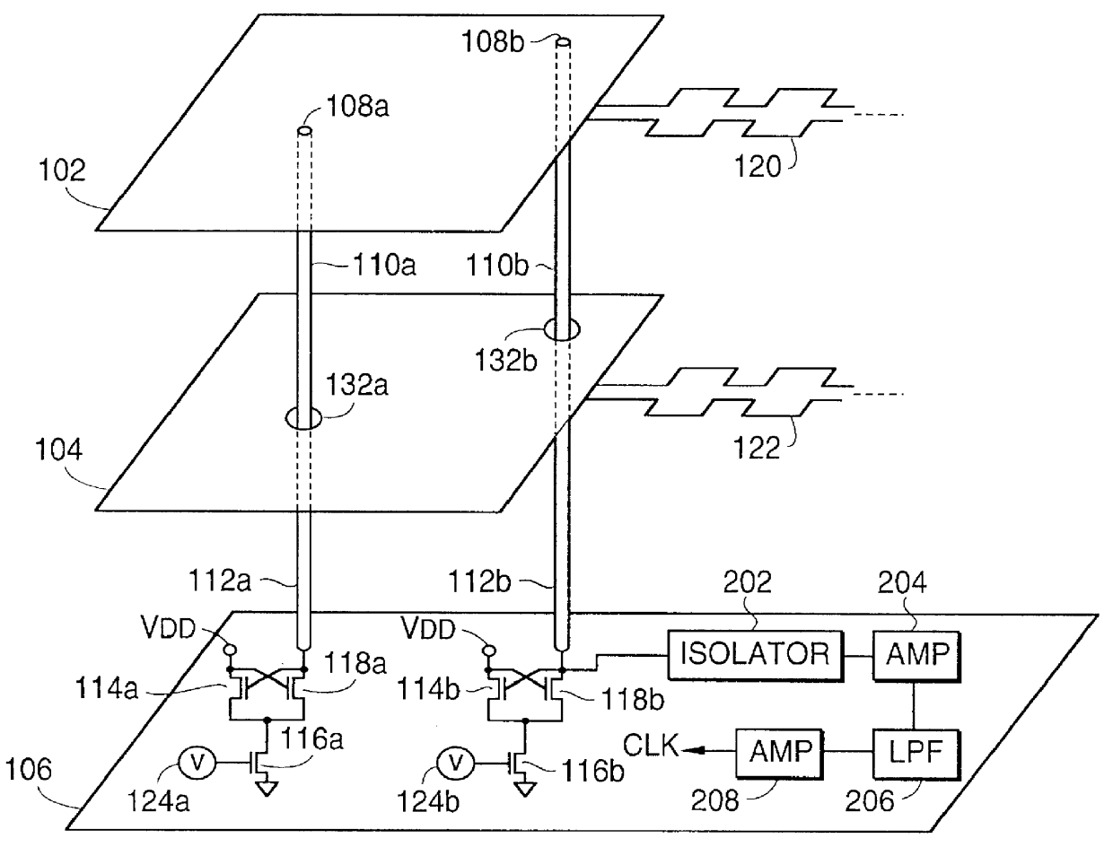
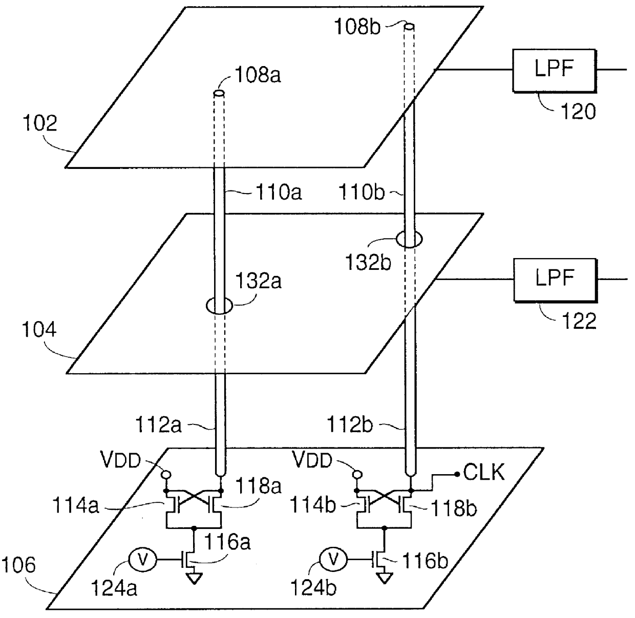
According to the present invention, there is provided a distributed clock generator, such as a resonator. No external clock generator is required. Furthermore, the invention does not operate by producing and transmitting a standing wave, so the prior art's restrictions of the system length to 1 / 8 or 1 / 16 of the wavelength are not applicable. The clock signal that is produced is available in a plurality of locations, simultaneously, without clock skew due to clock signal propagation.

Referring to FIG. 1, the preferred embodiment 100 shows a parallel plate microstrip patch resonator. The resonant cavity is established between an upper plate 102 and a lower plate 104, which are preferably made of aluminum or copper. The upper plate 102 is shown connected to a low-pass filter 120. This filter 120 is used to isolate the clock signal from the direct current ("DC") power supply. A similar filter 122 is shown connected to the lower plate 104. The low-pass filters 120, 122 of FIG. 1 are made ...


PUM


Abstract

A method and apparatus are described which eliminate the clock skew problems associated with routing clock signals throughout a circuit. Particularly well suited for Very Large Scale Integration ("VLSI") chips, the method and apparatus provide a resonator which is distributed across the circuit. This allows the clock to be accessed at a variety of locations without any propagation delay between the access points. The method for distributing a single, distributed clock signal to a plurality of clock connection points in a circuit comprises two steps. The first step is to generate the clock signal, such that the clock signal is available at a plurality of clock source points without propagation delay. The second step is to couple the plurality of clock source points to the plurality of clock connection points in the circuit.

Description

Not applicable.1. Field of the InventionThe invention disclosed broadly relates to the distribution of clock signals in circuits, and more particularly relates to synchronizing the clock signal in Very Large Scale Integration ("VLSI") circuits.2. Description of the Related ArtClock signals are usually responsible for coordinating the various operations performed in a circuit. Serious problems can result if the clock signals received by different parts of the circuit are not synchronized. A lack of synchronization can occur because because the different parts of the circuit are at different distances from the clock source. This causes the received clock signals to have different propagation delays and to be out of phase with each other. This problem, known as clock skew, can occur at the system level, the board level, and the chip level, and it becomes more severe as the circuit size increases and as the clock speed increases. At the chip level, trends in VLSI design are exacerbating...

Claims


Application Information

Patent Timeline
Patent Type & Authority Patents(United States)
IPC IPC(8): G06F1/10
CPCG06F1/10
Inventor WANN, HSING-JEN
Owner GOOGLE LLC
Why Eureka
Try Eureka