Air compressor aftercooler with automatic heated drain valve and start-up shut-off

a technology of air compressor and drain valve, which is applied in the direction of positive displacement liquid engine, lighting and heating apparatus, instruments, etc., can solve the problems of freezing and reducing or negating the brake action, and affecting the operation of the compressor

Inactive Publication Date: 2000-05-16
CHOVAN DALE A
View PDF4 Cites 18 Cited by
  • Summary
  • Abstract
  • Description
  • Claims
  • Application Information

AI Technical Summary

Benefits of technology

Yet another objective of the invention is to provide means for shutting off the drain valve when an engine or mot

Problems solved by technology

Indeed, if a mixture of compressed water and air flow through an orifice or valve, the air may drive discrete masses of water at high speed, which can erode internal surfaces causing noise

Method used


Image

  • Air compressor aftercooler with automatic heated drain valve and start-up shut-off

Examples


Embodiment Construction

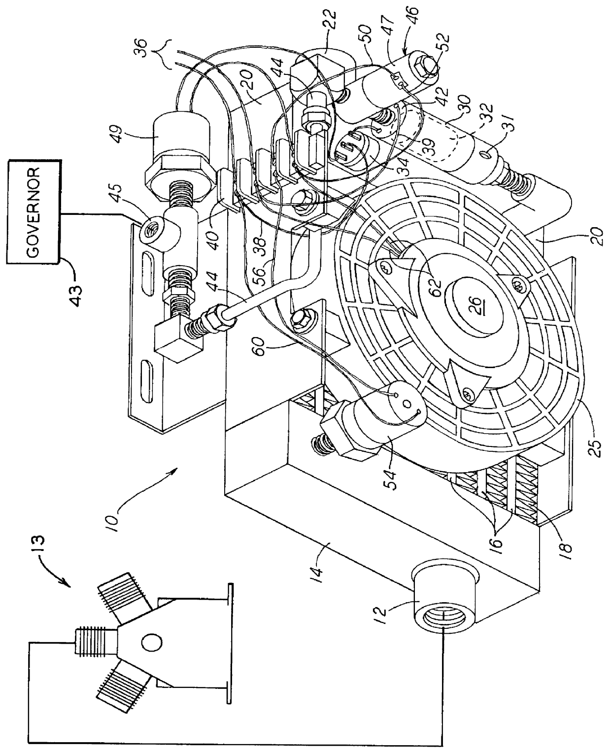
Referring now to the FIGURE of the drawing, an aftercooler 10 is shown having an input pipe 12 connected to receive hot, moisture laden gases from a compressor (not shown). The moisture laden gases enter a first header 14 of the aftercooler from pipe 12 where the gases collect and enter a plurality of tubes 16, with fins 18, connected to the header.

Tubes 16 extend to a second header 20 where compressed gases are collected after leaving the tubes for direction to an output pipe or nipple 22. Pipe 22 extends and is connected to a reservoir (not shown) for storing the compressed gases from aftercooler 10 which are now cooled to a temperature value near that of ambient. The reservoir supplies the stored air to systems using such air. The finned tubes provide the cooling which causes water vapor (moisture) contained in the gases received in first header 14 to condense to liquid water, which collects in a low end of second header 20. Additional cooling can be provided by a fan 25 driven b...


PUM


Abstract

A water release system includes a compact aftercooler connected to receive hot, moisture laden compressed air from a compressor having a load cycle under control of a governor. A water release valve is connected between a header of the aftercooler and an unloader pressure line connected to the governor. The valve ordinarily remains open until it receives a certain, pressure value signal from the unloader line which is effective to close the valve. A switch is located in pressure sensing relationship with the aftercooler, and a solenoid valve is electrically connected to the pressure sensitive switch and pneumatically connected between the water release valve and the governor. When the pressure sensed by the switch is somewhat above that at which the water release value ordinarily closes, the pressure sensitive switch closes to energize the solenoid valve and thereby open the same, after which the water release valve operates automatically to open and close in response to pressure and lack thereof in the unloader line.

Description

The present invention relates generally to aftercoolers connected to receive hot, moisture-laden compressed air from a compressor, and more particularly to a compact aftercooler for a variety of systems using compressed air at an air flow rate of less than about thirty cubic feet per minute (CFM). Compressed air systems are used extensively in the United States and throughout the world, and all such systems acquire moisture in the process of compressing ambient air. Condensing of this moisture to liquid water, and removal of the same from such systems is necessary, as explained hereinafter.Ambient outside air is drawn into an air compressor in the process of compressing air. All of the constituent gases and vapors in the ambient atmosphere, including moisture (water vapor), enter the compressor in the same proportion as the proportions in the outside ambient.For example, if a compressed air system provides air at a normal gauge pressure of 120.0 psi, and the ambient atmosphere has a...

Claims


Application Information

Patent Timeline
IPC IPC(8): F04B23/00B60T17/00
CPCB60T17/004
Inventor CHOVAN, DALE A.
Owner CHOVAN DALE A
Why Eureka
Try Eureka