Electric double layer capacitor

a double-layer capacitor and capacitor technology, applied in the direction of capacitors, multiple hybrid/edl capacitors, electrolytic capacitors, etc., can solve the problems that the requirement for implementing a thin-layer capacitor has not been satisfied, and the internal resistance of the conventional electric double-layer capacitor is small, so as to achieve the effect of low resistan

Inactive Publication Date: 2000-05-16
TOKIN CORP
View PDF15 Cites 25 Cited by
  • Summary
  • Abstract
  • Description
  • Claims
  • Application Information

AI Technical Summary

Benefits of technology

It is a further object of the invention to provide a novel thin-type electric layer capacitor having low resistance and method for manufacturing of the same.

Problems solved by technology

In fact, a conventional electric double layer capacitor having small internal resistance as well as of thin-type has not yet been implemented.
(1) In the electric double layer capacitor disclosed in JP Patent Kokai JP-A-6-84701 (1994), there is a problem that though it has small internal resistance but a requirement for implementing a thin-type capacitor has not been satisfied.

Method used


Image

  • Electric double layer capacitor
  • Electric double layer capacitor
  • Electric double layer capacitor

Examples


embodiment 1

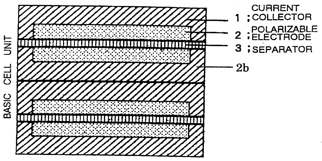
FIG. 1 is a sectional view of a structure of an electric double layer device in embodiment 1 according to the present invention, illustrating a laminated structure comprising two basic cell units of the electric double layer capacitor device.

Referring to FIG. 1, a current collector 1 (with a thickness of 100 .mu.m) contains a thermoplastic binder resin composed of polyvinyl butyrate wherein fine grains of carbon are dispersed. A polarizable electrode 2 (with a thickness of 40 .mu.m) contains a thermoplastic binder resin composed of polyvinyl butyrate wherein fine grains of activated carbon are dispersed. At an interface between the current collector 1 and the polarizable electrode 2, the thermoplastic binder resin is compatibilized by heating, to integrate the current collector 1 and the polarizable electrode 2 into one structure. Moreover, the polarizable electrode 2 placed facing with a separator 3 (with a thickness of 25 .mu.m) and the current collector 1 are disposed on the same...

embodiment 2

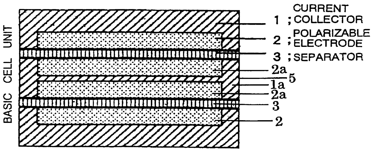
FIG. 2 is a sectional view of a structure of an electric double layer capacitor device according to embodiment 2 of the present invention wherein the electric double layer capacitor device comprises two basic cell units laminated as in embodiment 1.

This embodiment is different from embodiment 1 in that the polarizable electrode 2 (with a thickness of 40 .mu.m) is disposed on both sides of the current collector 1 (with a thickness of 100 .mu.m).

A method of manufacturing the electric double layer device according to the embodiment 2 is hereinafter described.

In this manufacturing method, as in the embodiment 1, a current collector and polarizable electrodes each having a specified shape are manufactured.

Subsequently, polarizable electrodes (with a thickness of 40 .mu.m) were laminated on both sides of the prepared current collector (with a thickness of 100 .mu.m) and were heated for one hour for press formation under the same condition (by a press pressure being 300 kg / cm.sup.2 and at ...


PUM

PropertyMeasurementUnit
thicknessaaaaaaaaaa
thicknessaaaaaaaaaa
thicknessaaaaaaaaaa

Abstract

A thin-type electric double layer capacitor having low internal resistance. This capacitor includes pairs of a current collector and polarizable electrode disposed opposite to each other with a separator being interposed therebetween. The current collector and polarizable electrode, each containing a thermoplastic binder resin and carbon, are made integral by compatibilization of the thermoplastic binder resins. Polarizable electrode faring with the separator is disposed on the plane as that for the current collector. In this capacitor, the glass-transition temperature of the thermoplastic binder resin contained in the current collector is lower than that of the thermoplastic binder resin contained in the polarizable electrode.

Description

The present invention relates to an electric double layer capacitor and more particularly to a thin-type electric double layer capacitor wherein contact resistance between a polarizable electrode and a current collector in the electric double layer capacitor is reduced and a manufacturing method for same.RELATED ARTA conventional electric double layer capacitor has been widely used as a capacitor of the thin-type having a large capacity as a backup device for microcomputer, memory, timer and the like, and there are vigorous research and development for an increase in performance. In order to reduce internal resistance of the electric double layer capacitor and to improve its characteristics, the following technologies have been disclosed.(1) For example, JP Patent Kokai JP-A-6-84701 (1994) discloses an electric double layer capacitor comprising multilayer structure electrodes wherein current collector and polarizable electrode materials are dispersed mutually therein and integrated ...

Claims


Application Information

Patent Timeline
Patent Type & Authority Patents(United States)
IPC IPC(8): H01G9/00H01G11/22H01G11/12H01G11/28H01G11/38H01G11/42H01G11/66H01G11/68H01G11/84H01G11/86
CPCH01G9/155H01G11/72Y10T29/417Y02E60/13H01G11/68H01G11/70H01G11/28H01G11/12
Inventor HARADA, GAKUSAKATA, KOJIKURIHARA, JUNKO
Owner TOKIN CORP
Why Eureka
Try Eureka