Apparatus suitable for transporting and storing nuclear fuel rods and methods for using the apparatus

a technology for nuclear fuel and apparatus, which is applied in the direction of nuclear engineering, nuclear nuclear elements, radioactive decontamination, etc., can solve the problems of insufficient insulation of the outside environment, gaps exacerbate the thermal problem, and excessive heat induced deformation and warpage of the box, etc., to achieve convenient and convenient handling, easy maintenance of the exterior, and high efficiency

Inactive Publication Date: 2000-05-16
SINGH KRIS
View PDF22 Cites 112 Cited by
  • Summary
  • Abstract
  • Description
  • Claims
  • Application Information

AI Technical Summary

Benefits of technology

It is therefore an object of the present invention to provide a dry storage apparatus for spent nuclear fuel rods which has the capability to store multiple fuel assemblies and provide axial as well as vertical support. It is another object to provide fuel basket assemblies which are capable of transporting heat to the outside surface and are rugged and convenient to handle, as well as capable of withstanding extreme handling accidents and environment events.
Another object is to provide an overpack structure which is capable of vertical orientation but resistant to large deceleration vents from impact due to a tipover or tornado missiles, as well as being an efficient heat rejecter, a highly effective gamma and neutron arrestor, and an all-weather enclosure vessel, with easily maintainable exterior.
Another object is to provide an improved closure system for the MPC which minimizes worker exposure to radiation and maximizes radiation shielding.
c) welding said plates to each other at their intersections so that all contiguous corners of the storage cells formed by said gridwork are completely connected so as to allow conduction heat transfer and to provide a rigid structure.

Problems solved by technology

In spite of the many attempts by other research and design teams, no one has proposed a multi-purpose canister or fuel basket having the capability to store multiple fuel assemblies and provide axial as well as vertical support, have the capability to transport the heat generated by the fuel assembled to its outside surface, be sufficiently rugged to enable convenient handling, and capable of withstanding handling accidents.
Furthermore, no one has provided a concrete overpack structure which effectively insulates the outside environment from the gamma and neutron radiation while effectively and efficiently rejecting heat to the atmosphere, while at the same time being sufficiently rugged to withstand an accidental tipover event, as well as earthquakes, tornadoes, and other extreme environmental events.
The thermal problem in a cask consists of rejecting the decay heat produced by the spent nuclear fuel such that the temperature of the fuel cladding remains below the threshold value at which long-term temperature effects would not degrade the cladding.
In other words, the gaps exacerbate the thermal problem in cask design in a most direct and significant manner.
Welding the sheathing to the box to create a sealed chamber for Boron carbide encased in aluminum leads to excessive heat induced deformation and warpage of the box.
For boxes made of low conductivity materials such as austenitic stainless steel, severe welding induced warpage is simply unavoidable.
In summary, the box / disk construction forces the designer to introduce gaps which are most detrimental to the transmission of heat.
Otherwise, the heat duty rating of the cask will be severely limited.
Some of the structural frailities of the box and disk design become clear when one considers that the deformation of the boxes and disks in the manufacturing process makes the condition of support at the box-hole interface largely uncertain.
Even under the ideal conditions of support, the inherent structural limitations of the box and disk design is easily understood when a horizontal drop event is considered.
Calculations show that stress levels in the boxes for a horizontal drop event typical of transport conditions are too high and raise the concern that under a horizontal drop event, the boxes will bulge, reducing the flux trap gap between them with direct consequence to the package's nuclear criticality characteristics.
After each lid is installed, welding machines are set up and the weld must be inspected, causing the operator to receive radiation exposure.

Method used


Image

  • Apparatus suitable for transporting and storing nuclear fuel rods and methods for using the apparatus
  • Apparatus suitable for transporting and storing nuclear fuel rods and methods for using the apparatus
  • Apparatus suitable for transporting and storing nuclear fuel rods and methods for using the apparatus

Examples


Embodiment Construction

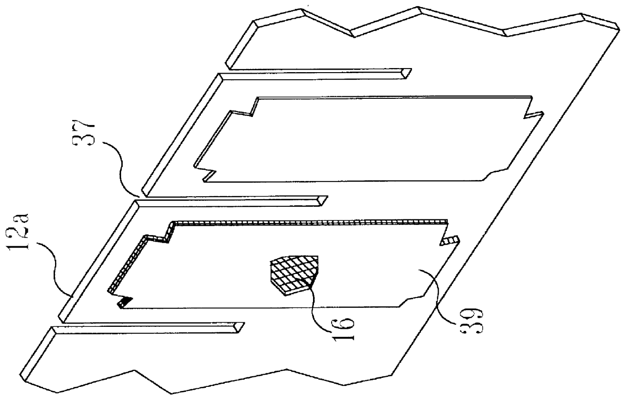
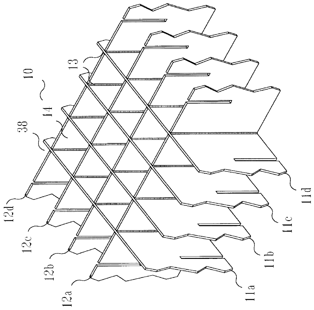
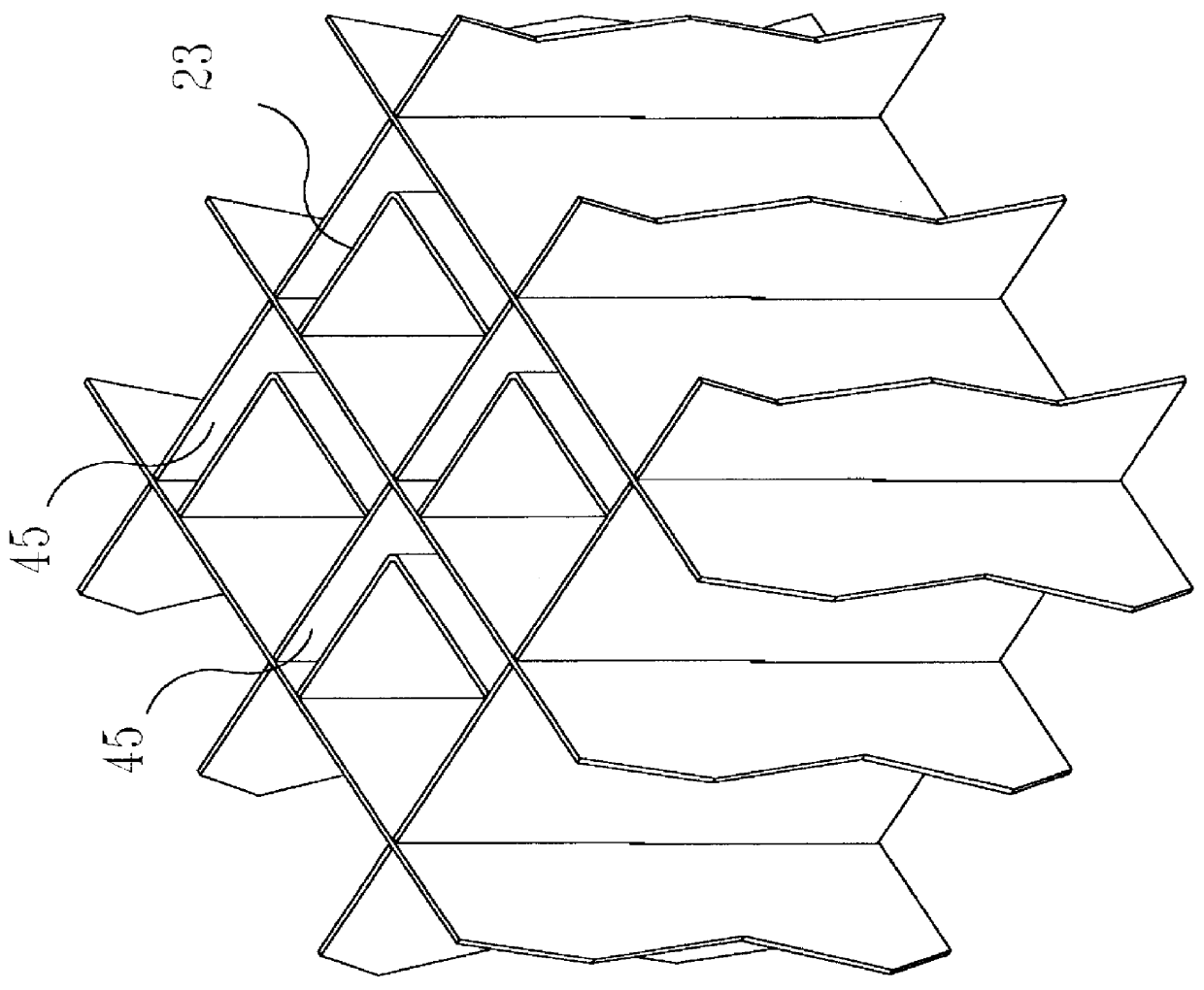
With reference to the drawings wherein like numerals designate like components of the invention throughout all of the several figures, fuel basket 10 is shown in FIGS. 2, 3, 4, 5, 6, 7, 8, 9, 10, 11, 12, 14, and 15. The basket 10 is formed from a honeycomb gridwork of plates 11a-11d and 12a-12d having neutron absorber material 16 positioned in areas which form walls of storage cells formed by the honeycomb structure. A portion of one plate 12a is shown in FIG. 1.

The invention also comprises the MPC 43, wherein a metal shell 19 cylindrically encircles the basket 10, shown in cross section in FIGS. 10, 11, 12, and 15.

The overpack aspect of the invention is shown in cross section in FIG. 13, and in combination with the MPC in the partial cross sectional, exploded view in FIG. 14.

The honeycomb structure of fuel basket 10 results in vertical cell openings 14 (also called "fuel cavities" or "storage cells"), each one of which is designed to hold one spent nuclear fuel assembly (not shown)...


PUM


Abstract

Apparatus suitable for transporting and storing nuclear fuel rods comprising a basket having storage cells formed from a honeycomb gridwork of metal plates in a rectilinear configuration, the plates welded to each other at their intersections so that all contiguous corners of the storage cells formed by the gridwork are completely connected so as to allow conduction heat transfer, the metal plates having neutron absorber material positioned in areas which form walls of the storage cells. Method of making an apparatus suitable for transporting and storing nuclear fuel rods comprising a) providing metal plates having slots and having neutron absorber material positioned on sides of the metal plates, b) arranging the plates so that the slots intersect to form a honeycomb gridwork of storage cells having contiguous corners and having the neutron absorbing material on sides of the storage cells, and c) welding the plates to each other at their intersections so that all contiguous corners of the storage cells formed by the gridwork are completely connected so as to allow conduction heat transfer and to provide a rigid structure.

Description

1. Field of the InventionThis invention relates to containers for storage and transportation of spent nuclear fuel.2. Description of the Prior ArtSpent nuclear fuel (SNF) discharged from reactors emits highly piercing gamma and neutron radiation and thermal energy. SNF is typically stored in deep pools filled with water to dissipate heat and to attenuate the gamma and neutron radiation generated by the fuel. An alternative to storing the SNF in water filled pools (wet storage) consists of the so-called dry storage concept wherein the SNF is stored in a configuration inside a heavy-walled vessel referred to as the "cask." Dry storage systems usually consist of two basic constituents, a multi-purpose canister (MPC) and an overpack. The term MPC refers to a fuel basket within an enclosure vessel. After SNF is placed in a fuel basket, the fuel basked is placed in an enclosure vessel, and the resultant MPC, which is the "fuel confinement system," is then placed into a neutron / gamma isola...

Claims


Application Information

Patent Timeline
Patent Type & Authority Patents(United States)
IPC IPC(8): G21F5/008G21F5/012G21C19/32G21F9/36
CPCG21F5/012
Inventor SINGH, KRISHNA P.
Owner SINGH KRIS
Why Eureka
Try Eureka