Magnetically driven agitator with magnetic rotation detector

a magnetic rotation detector and agitator technology, applied in the direction of mixers, chemistry apparatuses and processes, mixing, etc., can solve the problems of affecting the quality of the produ

Inactive Publication Date: 2000-05-23
MIXEL
View PDF25 Cites 64 Cited by
  • Summary
  • Abstract
  • Description
  • Claims
  • Application Information

AI Technical Summary

Problems solved by technology

In the known devices, this absence of mechanical connection between the drive shaft and the propelling screw may lead to errors in manipulation or blockages which cannot be revealed before the recipient is completely emptied.
As a mixture can be stirred for a relatively long period of time, of the order of several days and even of several weeks, if this omission is discovered at the end of manipulation, numerous working hours are lost, as well as a high value-added product.
Similarly, it may happen t

Method used


Image

  • Magnetically driven agitator with magnetic rotation detector
  • Magnetically driven agitator with magnetic rotation detector

Examples


Embodiment Construction

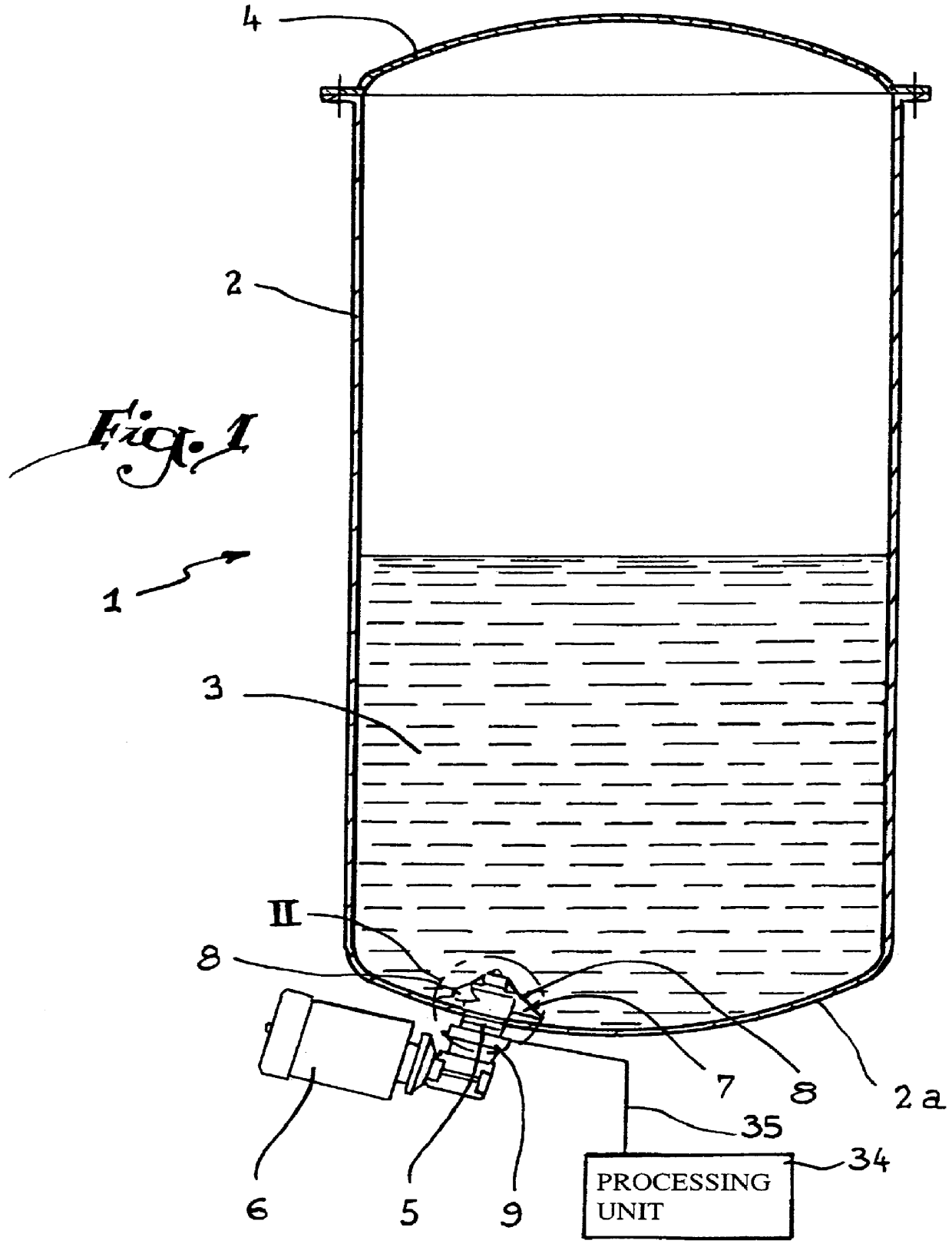
Referring now to the drawings, and firstly to FIG. 1, a recipient 1 is formed by a tank 2 containing a mixture 3, while a lid 4 is provided to close an upper opening of the tank. In the bottom wall 2a of the tank 2 there is disposed a collar 5 made of a magnetic material supporting a magnetic agitator comprising an electric drive motor 6, located outside the tank 2, and a propelling screw 7 disposed inside the tank in the mixture 3. Rotation of the screw 7 by the electric motor 6 results in a displacement of its blades 8 about an axis of rotation X-X', which has for its effect to stir the mixture 3.

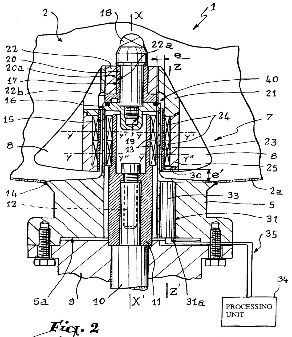
A bevel gear 9 is disposed at the outlet of the motor 6 and its driven shaft is constituted by a shaft 10 partially visible in FIG. 2. This shaft 10 is secured to a hollow shaft 11 by means of a fixing screw 12. It would also be possible to mount the motor 6 in direct engagement on a shaft 10, the use of a bevel gear not being indispensable.

The hollow shaft 11 bears two rows of permanent ...


PUM


Abstract

A magnetically driven agitator for a mixture contained in a recipient which agitator is supported by a collar hermetically mounted in a wall of the recipient and which collar is provided with a blind sleeve inside which is housed a drive shaft provided with a first magnetic coupling. A propelling screw is disposed around the blind sleeve and is provided with a second magnetic coupling adapted to cooperative with the first magnetic coupling for driving the propelling screw about an axis of rotation. A third magnetic element carried by the propelling screw is disposed opposite a cell for detecting the movement of the third coupling element during rotation of the propelling screw about the axis of rotation.

Description

1. Field of the InventionThe present invention relates to a magnetically driven agitator.2. Brief Description of the Related ArtAgitators are conventionally used for stirring a mixture contained inside a recipient in order to avoid a decantation or any other alteration of the mixture in the course of time. A magnetically driven agitator presents the advantage that the propelling screw that it comprises is set in motion by a magnetic coupling which takes place without physical contact between two rotating parts, such as the driven shaft of an electric motor and the propelling screw which is associated therewith. This makes it possible to dispose this shaft outside the recipient while the propelling screw is installed inside the recipient. Any danger of leakage at the level of the agitator may thus be set aside. This is particularly useful when the mixture is toxic or when pollution thereof by outside agents must be avoided, such as for example in the case of a medicinal composition.I...

Claims


Application Information

Patent Timeline
IPC IPC(8): B01F13/00B01F13/08
CPCB01F13/0827B01F33/4535
Inventor EYRAUD, PHILIPPEFLAVIEN, GUY
Owner MIXEL
Why Eureka
Try Eureka