Apparatus for generating an alternating magnetic field
- Summary
- Abstract
- Description
- Claims
- Application Information
AI Technical Summary
Benefits of technology
Problems solved by technology
Method used
Image

Examples
Embodiment Construction
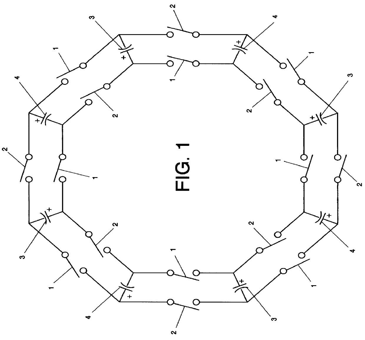
5.1 Refer first to FIG. 1, the simplified conceptual drawing of the dual current loop. Switches 1 and 2, eight of each, are arrayed physically in a loop surrounding the area through which the generated magnetic field is to pass, the field passing in the direction perpendicular to the page of the drawing. Capacitors 3, of which there are four, are connected, if of the polarized variety as shown, with their positive terminals "inside". Capacitors 4, of which there are again four, are similarly connected with their positive terminals "outside". The capacitors are kept charged by means not shown in FIG. 1.
5.2 In operation, current is caused to flow around the overall loop in alternating directions by first closing all switches 1 simultaneously, then opening them and closing switches 2 simultaneously and so forth. A complete current path around the loop can readily be traced, for either direction, by following a path from any "+" capacitor terminal, say, through a closed switch 1 or swit...
PUM
 Abstract
Description
Claims
Application Information