Permanent magnet material composition and structure for eddy current suppression in a nuclear magnetic resonance sensing apparatus

a technology of permanent magnet material and eddy current suppression, which is applied in the field of permanent magnet material composition and structure for eddy current suppression in nuclear magnetic resonance sensing apparatus, can solve the problems of significant and loss of rf power in the magn

Inactive Publication Date: 2000-05-30
WESTERN ATLAS INTERNAIONAL INC
View PDF2 Cites 45 Cited by
  • Summary
  • Abstract
  • Description
  • Claims
  • Application Information

AI Technical Summary

Problems solved by technology

If the permanent magnet material is electrically conductive, losses of RF power will occur as a result.
If the magnet is made from electrically conductive permanent magnet material, significant losses of RF power will occur as a result of eddy currents flowing in the magnet.
This outside metallic structure also serves as a shield against RF alternating electromagnetic fields penetrating into the permanent magnet and resulting in RF power losses in the magnet.
Although instrument in the Kleinberg et al '787 patent reduces eddy current losses in electrically conductive elements of the tool by shielding the permanent magnet, this concept has several significant drawbacks.
One such drawback is that the instrument's sensitive volume is only about 0.8 cm away from the tool surface and extends only to about 2.5 cm radially outward from the tool surface.
Measurements made by this instrument tool are therefore subject to large error caused by roughness in the wall of the wellbore, deposits of the solid phase of the drilling mud (called "mudcake") onto the wall of the wellbore in any substantial thickness, and by the fluid content of the formation in the invaded zone.
The basic disadvantage of the approach taken in the '884 and '761 patents is that the relatively large conducting surfaces will disturb the spatial distribution of the RF magnetic field while transmitting, and will reduce the signal to noise ratio ("S/N") while receiving NMR signals.
High magnitudes of eddy current loss restricts the Q of the antenna, thereby restricting the useful geometry of the logging instrument.
However, the particle size of the magnet material powders and material proportion, as well as the bonding process, generate significant eddy current losses within the conductive particles themselves and between them in the overall magnet structure.
Other disadvantages of using ferrite magnet material are that the ceramic-like material is very brittle and tends to chip.
This feature is particularly undesirable in the well logging environment, where logging instruments are placed under enormous hydrostatic pr

Method used


Image

  • Permanent magnet material composition and structure for eddy current suppression in a nuclear magnetic resonance sensing apparatus
  • Permanent magnet material composition and structure for eddy current suppression in a nuclear magnetic resonance sensing apparatus
  • Permanent magnet material composition and structure for eddy current suppression in a nuclear magnetic resonance sensing apparatus

Examples


Embodiment Construction

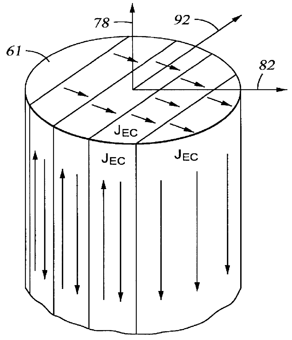
As explained in the description of the first embodiment of the invention, the overall electrical conductivity of a resin-bonded, powdered magnet including conductive magnetic material powder is related to the proportion of powdered magnetic material in the finished magnet. In the first embodiment of the invention, the magnetic powder proportion and resulting conductivity of the finished magnet is not controlled. Eddy current losses in the magnet are reduced by assembling the magnet from individual pieces (the blocks 61A in FIG. 3A) oriented to interrupt eddy currents flowing in the magnet. The thickness of any one of the blocks (61A in FIG. 3A) is limited to that which provides a minimum acceptable Q factor for the antenna, given the conductivity of the finished magnet and the frequency of the RF magnetic field. Equations for calculating the maximum thickness are shown in the description of the first embodiment of the invention.

In the first embodiment of the invention, the finished ...


PUM


Abstract

A nuclear magnetic resonance well logging apparatus, comprising an antenna for inducing a radio frequency magnetic field in earth formations surrounding the apparatus and for detecting nuclear magnetic resonance signals from the earth formations; and a magnet for inducing a static magnetic field within the earth formations. The magnet is formed from a powdered, electrically conductive permanent magnet material. The grain size of the magnet material small enough with respect to the frequency of the radio frequency magnetic field to substantially prevent intragranular power loss of the radio frequency magnetic field. The magnet is formed from electrically isolated blocks of the magnet material each having a thickness less than a skin depth of the radio frequency magnetic field within the magnet material. The boundaries between the blocks are oriented to interrupt flow of eddy currents in the magnet resulting from the radio frequency magnetic field. In a preferred embodiment, the magnet material comprises powdered, epoxy resin-bonded Samarium-Cobalt.

Description

1. Field of the InventionThe invention is related to the field of electromagnetic well logging instruments and methods. More specifically, the invention is related to an apparatus and method for reducing the effect of eddy currents induced in a permanent magnet upon the measurements made by nuclear magnetic resonance ("NMR") well logging instruments.2. Description of the Related ArtElectromagnetic well logging instruments include circuits connected to antennas which induce alternating electromagnetic fields in earth formations surrounding a wellbores, and include circuits which measure various electromagnetic phenomena which occur as a result of interaction of the alternating electromagnetic fields with the earth formations. Such electromagnetic phenomena relate to petrophysical properties of interest of the earth formations. One type of electromagnetic well logging instrument which suffers deleterious effects of eddy currents in electrically conductive elements of the logging instr...

Claims


Application Information

Patent Timeline
IPC IPC(8): G01V3/32G01R33/44G01V3/18G01R33/38G01R33/383
CPCG01N24/081G01V3/32G01R33/383
Inventor TAICHER, GERSH ZVIREIDERMAN, ARCADY
Owner WESTERN ATLAS INTERNAIONAL INC
Why Eureka
Try Eureka