Hydraulic bearing device

a bearing device and hydraulic technology, applied in the direction of bearings, bearing cooling, shafts and bearings, etc., can solve the problems of vibration circle, deterioration of bearing performance, and possible seizure of bearing metal

Inactive Publication Date: 2000-06-06
TOYODA MASCH WORKS LTD
View PDF16 Cites 11 Cited by
  • Summary
  • Abstract
  • Description
  • Claims
  • Application Information

AI Technical Summary

Problems solved by technology

This results in a vicious circle.
Continuation of such a vicious circle leads to deterioration of bearing performance and possible seizure of the bearing metal 30 with the rotating shaft...

Method used


Image

  • Hydraulic bearing device
  • Hydraulic bearing device
  • Hydraulic bearing device

Examples


first embodiment

[First embodiment]

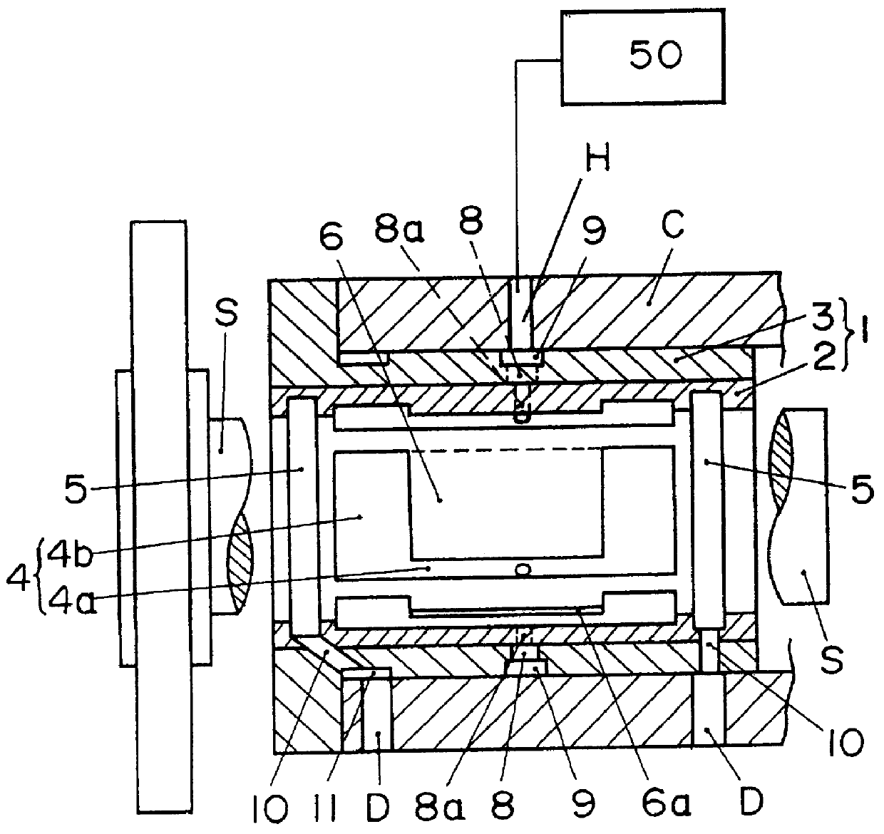
Preferred embodiments of a hydraulic bearing device according to the present invention will be described hereinafter with reference to the accompanying drawings. The hydraulic bearing device according to the present invention is employed, for instance, in a wheel spindle of a grinding machine as illustrated in FIG. 2. A main spindle casing C is provided with the hydraulic bearing device for rotatably supporting an outer peripheral surface of the wheel spindle, that is, a rotating shaft S.

A hydraulic bearing device according to a first embodiment of the present invention will be described.

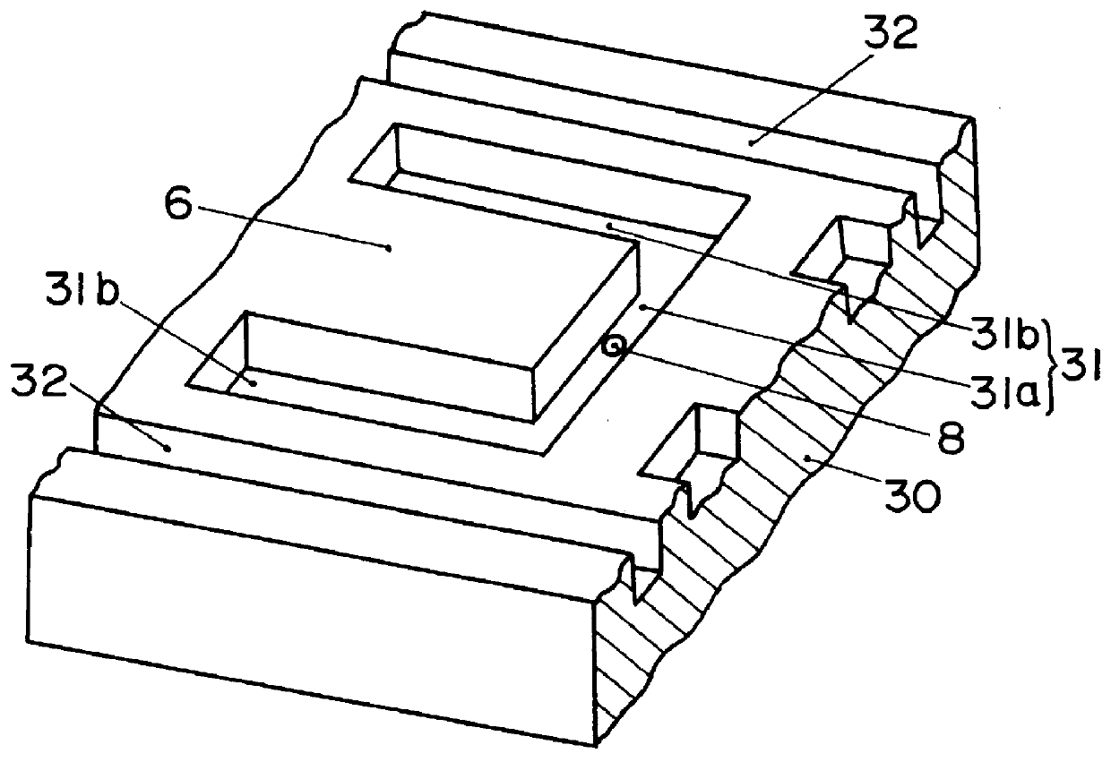
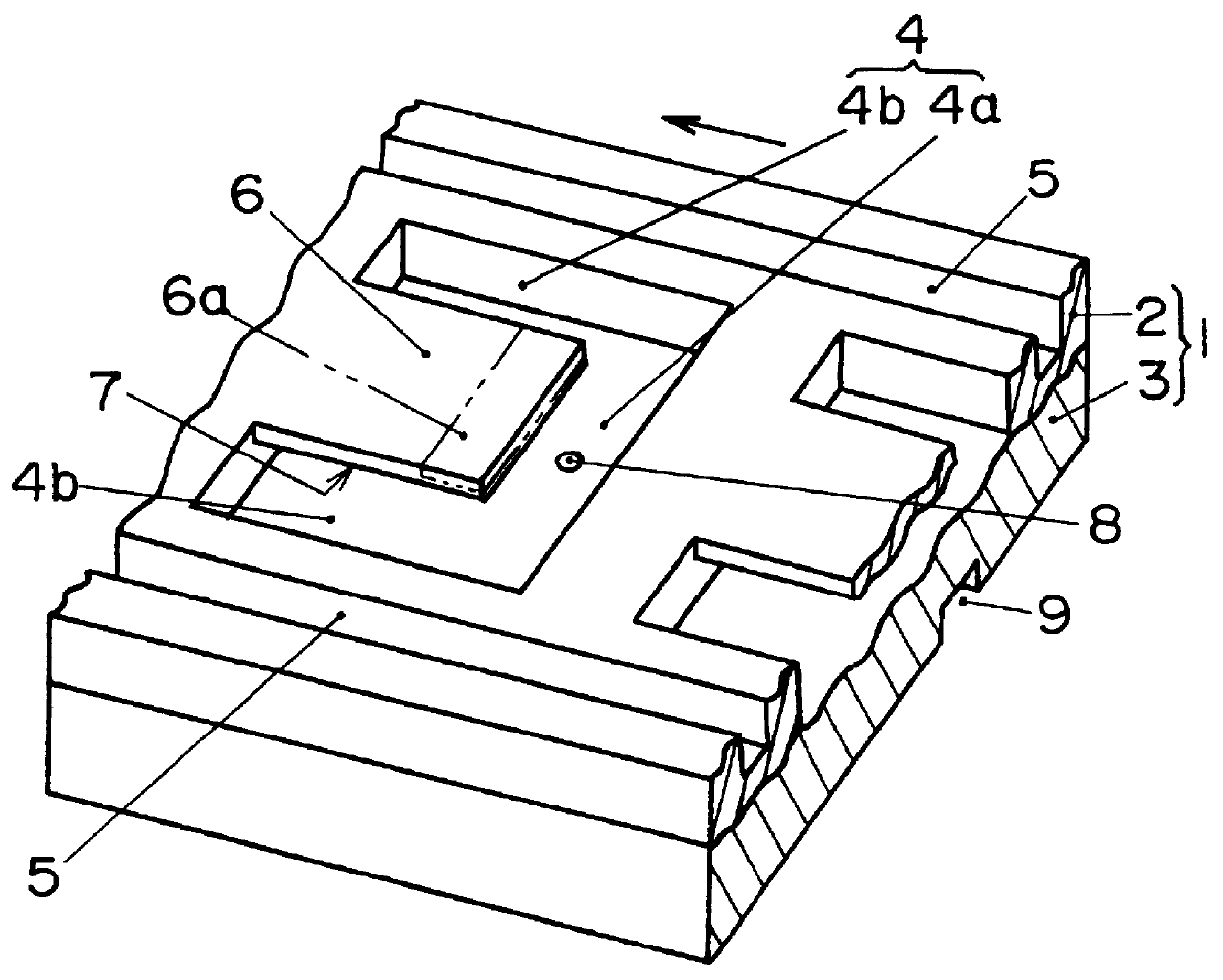
The hydraulic bearing device as illustrated in FIG. 2 has a bearing metal 1 that is composed of an inner sleeve 2 and a bearing casing 3. The inner sleeve 2 is formed in a cylindrical shape and rotatably supports the outer peripheral surface of the rotating shaft S. The inner sleeve 2 is press-fitted or shrinkage-fitted into the bearing casing 3 which is also formed in a cylindrica...

second embodiment

[Second embodiment]

A hydraulic bearing device according to a second embodiment of the present invention will now be described.

This hydraulic bearing device is constructed in the same manner as the hydraulic bearing device of the first embodiment except for the position of the oil supply hole 8, the shape of the leg portion 4b and the shape of those portions relating to drainage of lubricating oil. In the second embodiment, the oil supply hole 8 opens inevitably to the connecting portion 4a of the substantially U-shaped slot 4 (e.g. to a center of the connecting portion 4a as illustrated in the drawings).

As illustrated in FIG. 5, each leg portion of the substantially U-shaped slot 4 is composed of a first leg portion 4c connected with both ends of the connecting portion 4a and a second leg portion 4d formed separately from and extends parallel to the first leg portion 4c. The second leg portion 4d is located outward of the first leg portion 4c with respect to an axis of the rotating ...

third embodiment

[Third embodiment]

A hydraulic bearing device according to a third embodiment of the present invention will now be described.

This hydraulic bearing device is constructed in the same manner as the hydraulic bearing device of the first embodiment except for the oil supply hole 8 and the fluid flowing space 7 through which lubricating oil flows so as to cool the dynamic pressure generation land 6.

As illustrated in FIGS. 6, 7(a) and 7(b), a quadrilateral bearing surface area surrounded by the substantially U-shaped slot 4 constitutes the dynamic pressure generation land 6. Formed in a section of the outer peripheral surface of the inner sleeve 2 corresponding to the dynamic pressure generation land 6 are an appropriate number of communication grooves 14 that connect the leg portions 4b, 4b with each other. Referring to the drawings, the dynamic pressure generation land 6 in provided with three communication grooves 14. The communication grooves 14 extend along the axis of rotation and pa...


PUM


Abstract

A hydraulic bearing device includes a cylindrical bearing metal, a groove-like pocket, a dynamic pressure generation land, a fluid flowing space and an oil supply hole. The cylindrical bearing metal supports a rotating shaft. The pocket is formed in an inner peripheral surface of the bearing metal. The pocket defines the dynamic pressure generation land. The fluid flowing space is formed in the dynamic pressure generation land. The oil supply hole supplies fluid from a fluid pressure source to the pocket and the fluid flowing space. The dynamic pressure generation land which has been heated due to fluid friction is cooled by the fluid passing through the fluid flowing space formed in the dynamic pressure generation land. It is thus possible to inhibit thermal expansion of the hydraulic bearing device, especially the dynamic pressure generation land.

Description

INCORPORATION BY REFERENCEThe entire disclosure of Japanese Patent Application No. HEI 9-84622 filed on Mar. 19, 1997 including specification, drawings and abstract is incorporated herein by reference in its entirety.1. Field of the InventionThe present invention relates to a hydraulic bearing device that is mounted, for example, on a main spindle of a machine tool.2. Description of the Related ArtAs illustrated in FIG. 1, a previously employed hydraulic bearing device to be mounted on a main spindle of a machine tool or the like is provided with a bearing metal 30. Referring to rig. 1, a substantially U-shaped groove 31 is formed in a bearing surface of the bearing metal 30 which supports a rotating shaft such as the main spindle of the machine tool. An oil supply hole 8 having a throttle nozzle opens to a bottom surface of the substantially U-shaped groove 31. The substantially U-shaped groove 31 is composed of a connecting portion 31a that extends in an axial direction of the rot...

Claims


Application Information

Patent Timeline
IPC IPC(8): F16C33/04F16C37/00F16C32/06F16C33/10F16C17/00F16C17/24F16C17/02F16C32/00
CPCF16C17/02F16C17/24F16C37/002F16C33/1075F16C32/0659F16C32/06F16C39/04
Inventor INAGUMA, YOSHIHARUSUGIYAMA, KAZUHISA
Owner TOYODA MASCH WORKS LTD
Why Eureka
Try Eureka