Method for recovery and reuse of gas

a gas recovery and gas technology, applied in the field of gas recovery and reuse, can solve the problems of gas that is present in the process, is an expensive gas, or poses some type of environmental hazard,

Inactive Publication Date: 2000-07-18
ENTEGRIS INC
View PDF6 Cites 71 Cited by
  • Summary
  • Abstract
  • Description
  • Claims
  • Application Information

AI Technical Summary

Problems solved by technology

In many other processes, however, the gas that is present in the process, either as initially supplied to the process vessel or chamber or as generated during the process, is an expensive gas, a gas in limited supply or a gas which poses some type of environmental hazard, including hazards to humans and animals.
There is, however, a large excess of xenon gas remaining in the chamber over that which is now sequestered by being sealed in the light bulbs.
While the venting of xenon does not pose an environmental hazard, xenon is a rare and quite expensive gas and any quantity of xenon vented to the atmosphere is thereafter unrecoverable.
Venting, therefore, represents a substantial loss of a valuable and costly resource, xenon gas, so the bulb manufacturers want to recover as much of the excess xenon as possible after each batch of bulbs is manufactured and recycle it for reuse in the manufacture of subsequent batches of light bulbs.
Such processes have commonly involved cryogenic steps, are quite complex and expensive to operate and the gas recovery is often relatively low.
For relatively low cost items such as light bulbs, of course, such costs cannot be justified and the xenon gas has, in the past, usually been vented and lost.
Such a process requires extensive gas separation facilities, such as membrane and zeolite separators, and leaves the process gas with residual purge gas contamination.
However, such processes have proved to be unsatisfactory beyond very short time periods (i.e., over more than a few iterations of the manufacturing process)...

Method used


Image

  • Method for recovery and reuse of gas
  • Method for recovery and reuse of gas

Examples


Embodiment Construction

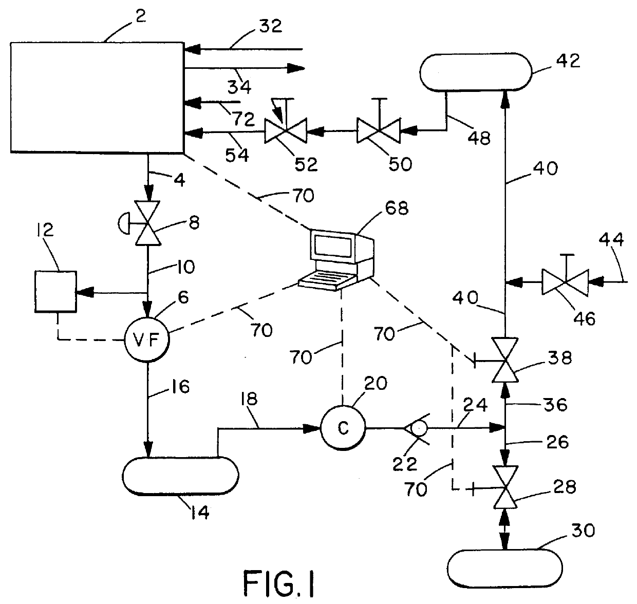
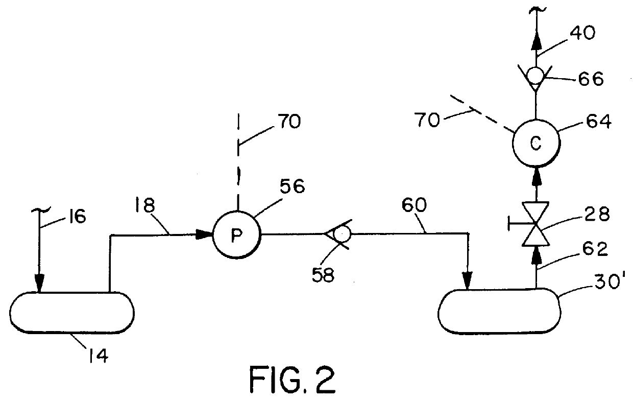
The methods of this invention will be best understood by reference to the drawings, which illustrate schematically two preferred alternative embodiments of the invention. Considering first the embodiment of FIG. 1, an openable gas-tight manufacturing or reaction chamber, such as the chamber used to fill and heat seal light bulbs as described above, is illustrated at 2. The nature of this chamber or the manufacturing or reaction operation performed in it is not critical to the present invention, other than for the fact that it involves the presence or use of the gas, and at its conclusion there will be a significant amount of excess gas which must be recovered from the chamber 2. The exact amount of gas to be recovered is similarly not critical, although in many cases the excess gas to be removed represents a larger quantity (in many cases a much larger quantity) of gas than the quantity of gas actually utilized and consumed or sequestered in the operation. In the exemplary manufactu...


PUM


Abstract

A gas recovery and reuse/recycle method is disclosed which can readily and economically recover valuable and/or environmentally hazardous gases from a manufacturing or chemical process and then return the gas to the process for reuse, and repeat this many times without significant contamination or degradation of the gas or the produced products. All gas transport, compression and storage equipment is designed and maintained so that it is non-contaminating to the process gas. Commonly the process gas will be a Group VIII gas, preferably He, Ne, Kr or Xe, or a gas which comprises a hazard to the ambient environment or beings therein, such as a carbon oxide gas, a halocarbon gas, an acid-precursor gas, a biologically hazardous gas, or a radioactive gas.

Description

1. Field of the InventionThe invention herein relates to operation of manufacturing processes and equipment in which a valuable or environmentally hazardous gas is utilized. More particularly, it relates to methods for recovery from and subsequent reuse of that gas in such processes and equipment.2. Description of the Prior ArtThere are numerous manufacturing processes in which gases are used as reactants or to provide a process atmosphere, but in which a significant amount of free excess gas remains upon completion of the process. If the gas is both inexpensive and non-hazardous to the environment, the excess gas can simply be vented to the ambient environment. Typical examples of such gases are air, oxygen, nitrogen, water vapor and, in some cases, argon.In many other processes, however, the gas that is present in the process, either as initially supplied to the process vessel or chamber or as generated during the process, is an expensive gas, a gas in limited supply or a gas whic...

Claims


Application Information

Patent Timeline
IPC IPC(8): B01D53/00C01B23/00H01J9/52H01J9/00
CPCB01D53/00C01B23/001H01J9/52B01D2256/18Y10T137/469Y02W30/82
Inventor SPIEGELMAN, JEFFREY J.SHOGREN, PETER K.
Owner ENTEGRIS INC
Why Eureka
Try Eureka