Brake system for a motor vehicle

a technology for brake systems and motor vehicles, applied in brake control systems, brake systems, vehicle components, etc., can solve problems such as unfavorable vehicle safety, unfavorable vehicle safety, and inability to over-brake rear axles

Inactive Publication Date: 2000-07-25
ROBERT BOSCH GMBH
View PDF11 Cites 16 Cited by
  • Summary
  • Abstract
  • Description
  • Claims
  • Application Information

AI Technical Summary

Problems solved by technology

The rear axle cannot be overbraked, however, because the valves of the rear wheel brakes continue to be supplied with current via separate circuits, and the pressure in the rear axle brakes is limited.
As a result of the measures indicated above for shutting down the control function of the ABS and EBV controllers in most cases when a defect occurs, unwanted situations can occur during braking operations, because, without the control function, large slip values can occur at the wheels.
At large slip values, the wheels are no longer able to transfer lateral guide forces.
As a result, the steerability and the stability of the vehicle are lost during these high-slip phases.
In addition, locking wheels can be permanently damaged by the intense abrasion which occurs during braking.

Method used


Image

  • Brake system for a motor vehicle
  • Brake system for a motor vehicle
  • Brake system for a motor vehicle

Examples


Embodiment Construction

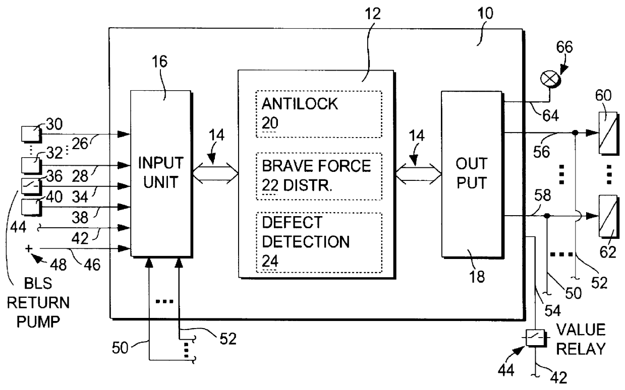
FIG. 1 shows an overall block circuit diagram of a brake system, in which the method according to the invention is used. A control unit it is shown, which includes at least one microcomputer 12. This is connected by way of a bus system 14 to an input unit 16 and an output unit 18 for the exchange of information and data. In a preferred exemplary embodiment, microcomputer 12 includes an antilock controller 20, a braking force distribution controller 22, and a defect detection unit 24. The main functions of these controllers and of the defect detection unit are known from the state of the art cited above.

In other advantageous exemplary embodiments, microcomputer 12 includes only antilock controller 20 and defect detection unit 24 or only braking force distribution controller 22 and defect detection unit 24.

Input lines 26-28 from speed sensors 30-32 at the front and rear axles of the vehicle, an input line 34 from a brake pedal switch 36, an input line 38 from a return pump 40 of the b...


PUM


Abstract

PCT No. PCT/DE96/00333 Sec. 371 Date Oct. 9, 1996 Sec. 102(e) Date Oct. 9, 1996 PCT Filed Feb. 28, 1996 PCT Pub. No. WO96/30243 PCT Pub. Date Oct. 3, 1996A brake system for a motor vehicle is proposed, which is equipped with an antilock controller and/or electronic braking force distribution control. When a defect occurs, these control systems are turned off only when necessary for safety reasons. When defects of any other type occur, the controls continue to operate on an emergency basis.

Description

STATE OF THE ARTThe invention pertains to a brake system for a motor vehicle wherein the ABS and / or the EBV are deactivated when defects in the electronic control system are detected.Modern brake systems for motor vehicles include not only conventional hydraulic or pneumatic brakes but also supplemental electronic functions such as antilock protection (ABS) and / or electronic braking force distribution (EBV) between the front and rear axles. These supplemental functions assist the driver during the braking process and improve the stability and steerability of the vehicle in braking situations. For safety reasons, measures must be taken to check out the functionality of the electronic control unit which carries out the supplemental functions and also to check out the mechanical and electrical components.For a hydraulic brake system, for example, it is known from SAE Paper 890970, "Electronic Control Unit of the Sumitomo Electronic Antilock System", that, to find a defect, it is possib...

Claims


Application Information

Patent Timeline
Patent Type & Authority Patents(United States)
IPC IPC(8): B60T8/88B60T8/92B60T8/00B60T8/1766
CPCB60T8/885B60T2270/402B60T2270/416B60T8/00
Inventor KORNHAAS, ROBERTGOTTWICK, ULRICH
Owner ROBERT BOSCH GMBH
Why Eureka
Try Eureka