Centrifugal blower impeller, especially for a heating and ventilating, and/or air conditioning, system for a motor vehicle

a centrifugal blower and impeller technology, which is applied in the direction of liquid fuel engines, vessel construction, marine propulsion, etc., can solve the problems of mechanical strength and a certain number of limitations, and achieve the effects of reducing mechanical properties, increasing mechanical rigidity of the arms, and enhancing mechanical strength of the whole impeller

Inactive Publication Date: 2000-08-01
VALEO SYST THERMIQUES
View PDF25 Cites 15 Cited by
  • Summary
  • Abstract
  • Description
  • Claims
  • Application Information

AI Technical Summary

Benefits of technology

One of the objects of the invention is to enhance the mechanical strength of the whole impeller, particularly as regards to the arms, in such a way as to increase the mechanical rigidity of the arms, and / or to enable the choice of material to be widened to include plastics material having reduced mechanical properties.

Problems solved by technology

These impellers are generally made from one piece, in a molded synthetic material, which imposes a certain number of limitations as regards to mechanical strength and moldability during A design of the various parts of the impeller.

Method used


Image

  • Centrifugal blower impeller, especially for a heating and ventilating, and/or air conditioning, system for a motor vehicle
  • Centrifugal blower impeller, especially for a heating and ventilating, and/or air conditioning, system for a motor vehicle
  • Centrifugal blower impeller, especially for a heating and ventilating, and/or air conditioning, system for a motor vehicle

Examples


Embodiment Construction

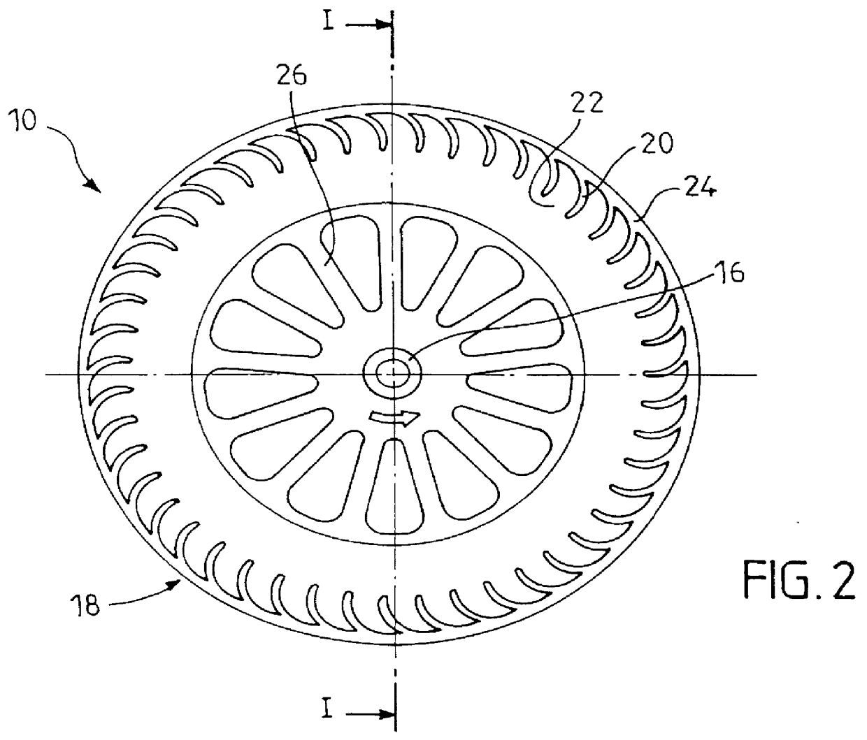
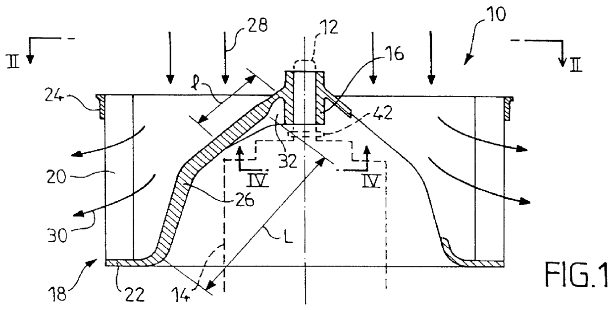
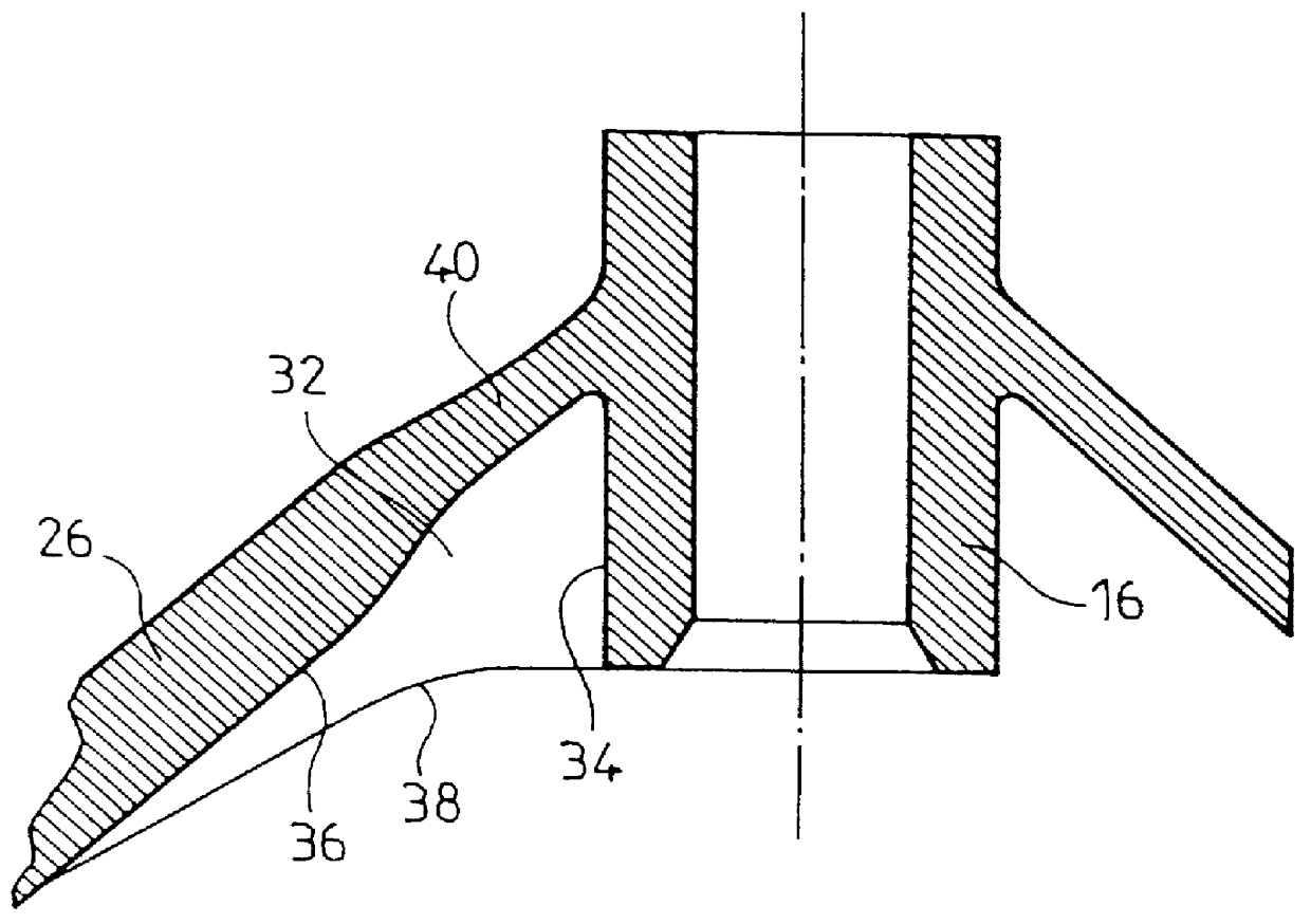
FIGS. 1 and 2 show generally a centrifugal blower impeller 10, which is typically made in one piece by injection molding in a suitable synthetic resin. This impeller is designed to be fitted on the shaft 12 of a drive motor 14, by means of a hub 16 into which the shaft 12 is force fitted.

The impeller 10 has the general form of a flattened cylinder, the overall diameter of which is greater than its height. A typical example of such an impeller, which is of course not limiting, has an overall diameter of 140 mm for a height of the cylindrical portion of 70 mm.

The outer part of the blower impeller 10 comprises a circular peripheral crown portion 18, carrying a large number of vanes or blades 20. The individual vanes are joined together by a common element 22 in the form of a circular crown element or ring, this being on the lower side as shown in FIG. 1; while on the other side, the vanes are joined together by a cylindrical stiffening element 24. The peripheral crown portion 18 is joi...


PUM


Abstract

A centrifugal blower impeller for a vehicle heating and ventilation system has a central hub, a peripheral crown having a set of vanes for drawing the air axially through the crown, to deliver the air radially towards the outside, and a set of arms, spaced apart at regular intervals and joining the hub to the crown. This set of arms defines a generally concave bowl-shaped envelope, with the arms being joined to the hub in the center of the bowl and with the crown at its periphery. At least some of the arms have reinforcing ribs close to the junction between the arm and the hub. Each rib lies in an axial plane and is on the side of the arm corresponding to the concavity of the bowl.

Description

This invention relates to centrifugal blower impellers, such as those which, in particular, incorporated in the blowers of systems for heating and ventilating, and or air conditioning, in motor vehicles.It is well known that such impellers have a central hub which is arranged to be mounted on a motor shaft, with a peripheral crown having a succession of vanes or blades for aspirating air axially through the interior of the crown and to deliver it radially towards the outside, together with a set of arms which join the hub to the peripheral crown. These impellers are generally made from one piece, in a molded synthetic material, which imposes a certain number of limitations as regards to mechanical strength and moldability during A design of the various parts of the impeller. It will easily be understood that the arms are subjected to high mechanical stresses, which have to be taken into account during design and choice of material.DISCUSSION OF THE INVENTIONOne of the objects of the...

Claims


Application Information

Patent Timeline
Patent Type & Authority Patents(United States)
IPC IPC(8): F04D25/02F04D25/08F04D29/28
CPCF04D25/082F04D29/281F04D29/5806
Inventor GRONIER, PASCALEBOUCHERET, BERNARDCLAUZEL, JEROME
Owner VALEO SYST THERMIQUES
Why Eureka
Try Eureka