Decoupled switched current temperature circuit with compounded DELTA V be

a technology of switching current temperature and compounded delta, which is applied in the direction of heat measurement, pulse technique, instruments, etc., can solve the problems of inability to properly use off-chip temperature measurement, difficult to maintain the precision of the ratio, and increase the size of the cell

Inactive Publication Date: 2000-08-01
ANALOG DEVICES INC
View PDF5 Cites 88 Cited by
  • Summary
  • Abstract
  • Description
  • Claims
  • Application Information

AI Technical Summary

Benefits of technology

The invention results from the realization that a more effective switched current temperature circuit with compounded .DELTA.V.sub.be in which one or both of the temperature sensing elements (including a PN junction and a reference voltage circuit) can be remote from the rest of the circuit is achieved by applying switched ratioed currents to a PN junction to develop a .DELTA.V.sub.be relative to the reference voltage circuit and selectively switching the PN junction and reference voltage circuit outputs between first and second input capacitors to an inverting amplifier.
This invention features a decoupled switch current temperature circuit with compounded .DELTA.V.sub.be including an amplifier having an inverting input with corresponding non-inverting output and a non-inverting input with a corresponding inverting output. There is a PN junction connected to the non-inverting input through a first capacitor and a voltage reference circuit connected to the inverting input thro...

Problems solved by technology

Increased .DELTA.V.sub.be can be obtained by increasing the ratio but doubling the .DELTA.V.sub.be requires squaring the ratio of the areas which increases the size of the cell and makes the precision of the ratio difficult to maintain.
All of these dual j...

Method used


Image

  • Decoupled switched current temperature circuit with compounded DELTA V be
  • Decoupled switched current temperature circuit with compounded DELTA V be
  • Decoupled switched current temperature circuit with compounded DELTA V be

Examples


Embodiment Construction

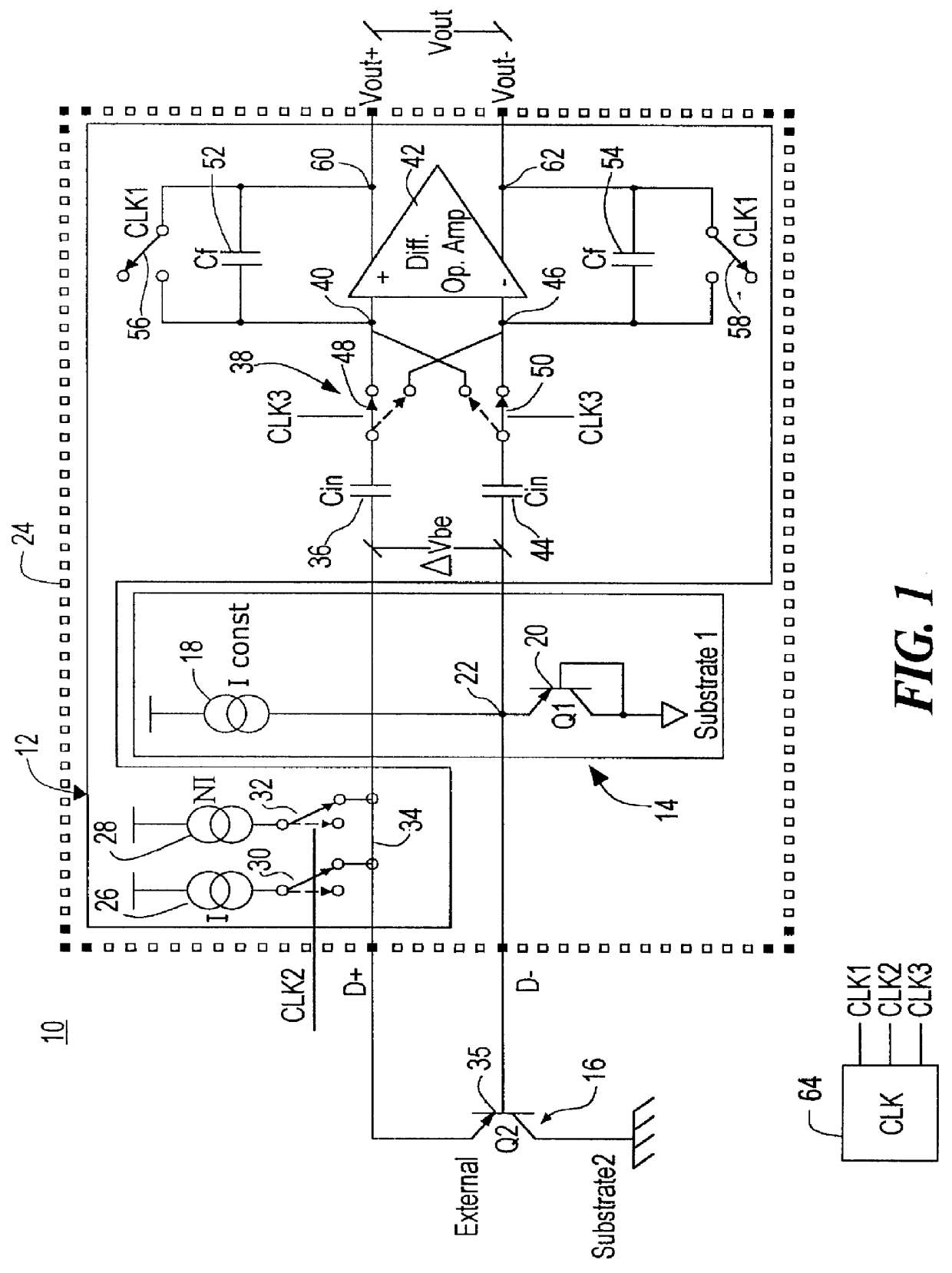
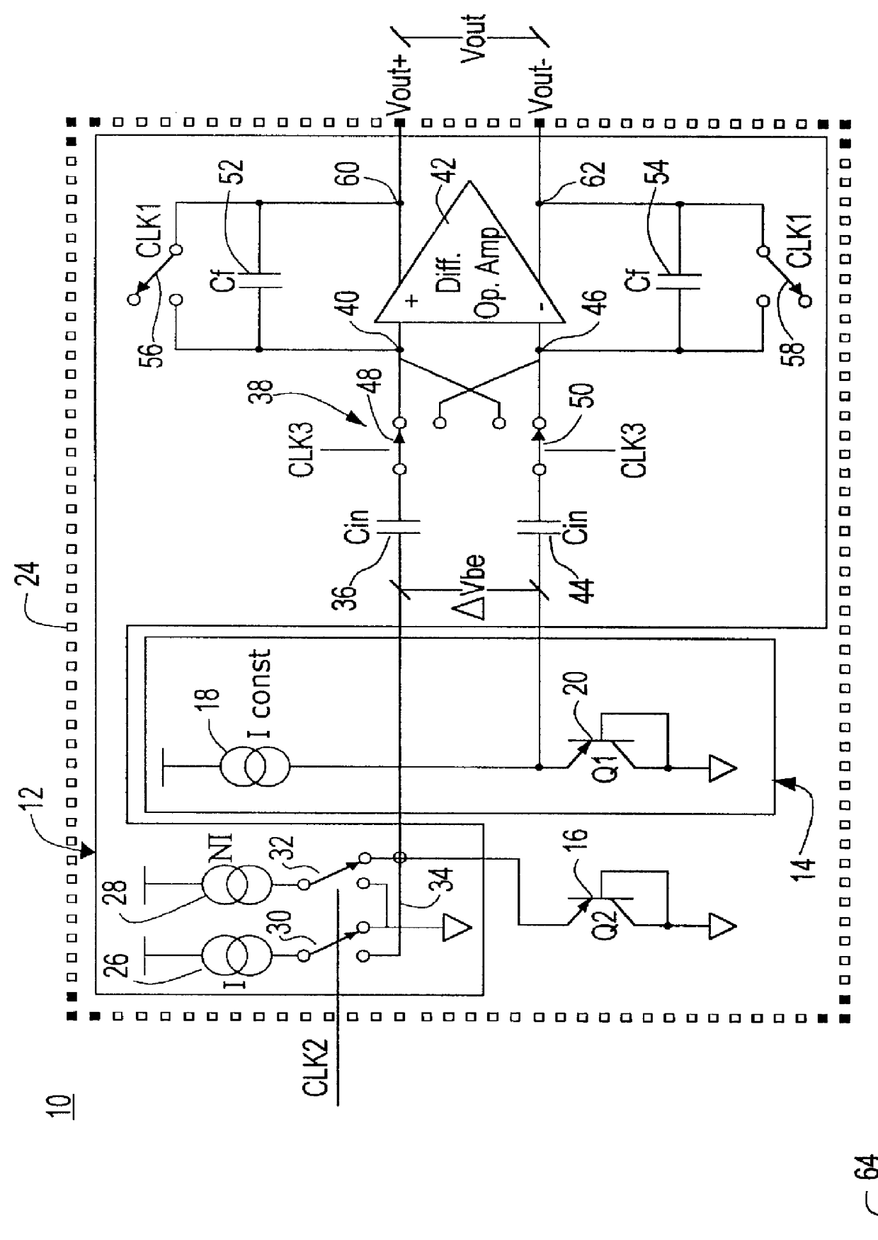
There is shown in FIG. 1a decoupled switched current temperature circuit with compounded .DELTA.V.sub.be 10 according to this invention which includes a signal processing circuit 12 and temperature sensing elements including a reference voltage circuit 14 and PN junction 16. In this particular embodiment voltage reference circuit 14 actually includes a current source 18 providing I.sub.constant and a PN junction 20 at whose emitter output, terminal 22, the reference voltage appears. The voltage reference circuit 14 is not limited to such a device as any voltage reference circuit would do. The voltage reference at terminal 22 may be any desired voltage including ground. The PN junction 16 is decoupled from the voltage reference circuit 14 and the rest of the signal processing circuit 12. By decoupled is meant that it is not necessary for it to be a matched transistor on the same integrated circuit chip; it may be a different component entirely and be entirely remote from the voltage ...


PUM


Abstract

A decoupled switched current temperature circuit with compounded DELTA Vbe includes an amplifier having an inverting input with corresponding non-inverting output and a non-inverting input with a corresponding inverting output; a PN junction connected to the non-inverting input through a first input capacitor and a voltage reference circuit is connected to the inverting input through a second input capacitor; a current supply includes a low current source and a high current source; a switching device applies the high current source to the PN junction and applies the low current source to the PN junction for providing the DELTA Vbe of the PN junction to the first capacitor; a first feedback capacitor is interconnected between the inverting output and the non-inverting input and a second feedback capacitor is interconnected between the non-inverting output and inverting input of the amplifier to define the gain on each of the inputs to produce a differential voltage across the outputs representative of the temperature of the PN junction; first and second reset switching devices discharge the first and second feedback capacitors, respectively, and a multi-phase switched device alternately interchanges the connection of the first and second input capacitors with the amplifier inputs for compounding the single DELTA Vbe .

Description

This invention relates to a decoupled switched current temperature circuit with compounded .DELTA.V.sub.be.BACKGROUND OF INVENTIONV.sub.be, the base to emitter voltage of a PN junction, is complementary to absolute temperature (CTAT) ##EQU1## where K is a constant, T is absolute temperature, q is charge, I is the collector current and I.sub.s is the saturation current. .DELTA.V.sub.be, the difference between the V.sub.be 's of two PN junctions, is proportional to absolute temperature (PTAT) ##EQU2##It is this relationship that underlies the use of PTAT cells to measure temperature. In one approach the cell uses two PN junctions of different areas ratioed by N and supplied with the same current to develop .DELTA.V.sub.be as shown by Paul Brokaw, "A Simple Three-Terminal IC Bandgap Reference", Solid-State Circuits, Vol. SC-9, pp. 388-393 (December 1974). This works well but the ratio of the areas must be carefully controlled to ensure accuracy. Increased .DELTA.V.sub.be can be obtaine...

Claims


Application Information

Patent Timeline
IPC IPC(8): G01K7/01
CPCG01K7/01
Inventor MIRANDA, JR., EVALDO MARTINOTUTHILL, MICHAEL G.BLAKE, JOHN
Owner ANALOG DEVICES INC
Why Eureka
Try Eureka