

Phosphor, its manufacturing method and plasma display panel
- Summary
- Abstract
- Description
- Claims
- Application Information
AI Technical Summary
Benefits of technology
Problems solved by technology
Method used
Image

Examples
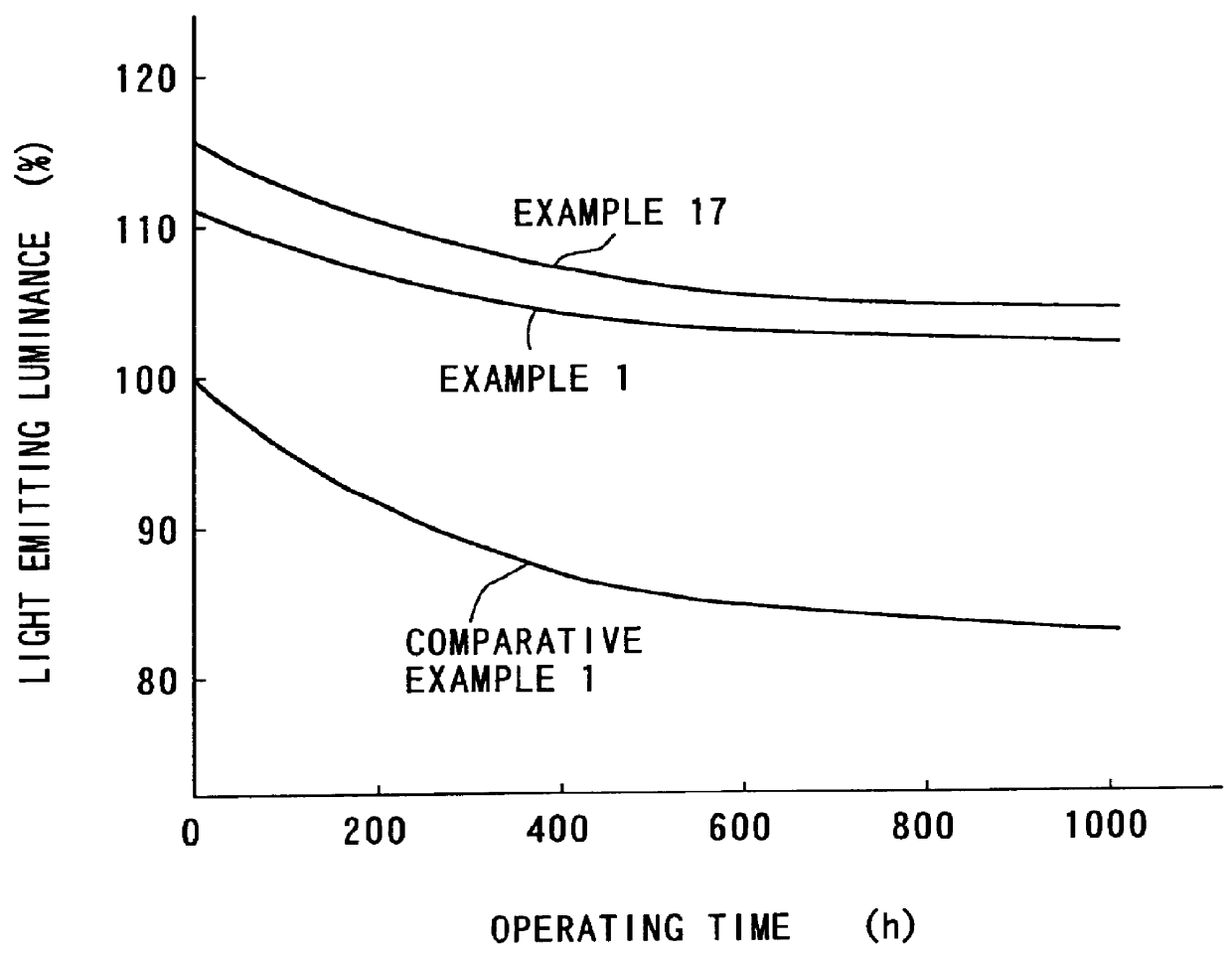
examples 17 to 20
1.0 part of alumina fine powder (particle diameter 50 nm) is injected into 500 parts of pure water and is stirred for 30 minutes so that the alumina fine powder is uniformly dispersed. Further, 100 parts of blue light emitting BaMg.sub.2 Al.sub.14 O.sub.24 :Eu are injected and stirred for about 60 minutes and the surfaces of phosphor particles are uniformly covered with alumina fine particles. Next, the phosphor is recovered by filtration and is dried. The phosphor is then burned for two hours at 500.degree. C. in the atmosphere. Thus, the phosphor particles having the covered surfaces of an Example 17 are obtained.
As results of an analysis and a surface observation using an electron microscope, the surfaces of the obtained phosphor particles are uniformly covered with 1.0 weight % of alumina fine particles.
Similar to the Example 17, phosphor particles in an Example 18 are obtained except that 4.0 parts of magnesium oxide fine powder (particle diameter 20 nm) instead of alumina are ...
examples 21 to 24
0.5 part of magnesium oxide (particle diameter 20 nm) is injected into 500 parts of pure water and is stirred for 30 minutes so that magnesium oxide fine powder is uniformly dispersed. Further, 100 parts of green light emitting phosphor of Zn.sub.2 SiO.sub.4 :Mn are injected and stirred for about 60 minutes and the surfaces of phosphor particles are uniformly covered with the magnesium oxide fine powder. Next, the phosphor is recovered by filtration and is dried. The phosphor is then burned for two hours at 400.degree. C. in the atmosphere. Thus, the phosphor particles having the covered surfaces of an Example 21 are obtained.
As results of an analysis and a surface observation using an electron microscope, the surfaces of the obtained phosphor particles are uniformly covered with 0.5 weight % of magnesium oxide fine particles.
Similar to the Example 21, phosphor particles of an Example 22 are obtained except that 4.5 parts of alumina fine powder (particle diameter 50 nm) instead of t...
examples 25 to 28
0.1 part of barium oxide fine powder. (particle diameter 90 nm) is injected into 500 parts of pure water and is stirred for 30 minutes so that the barium oxide fine powder is uniformly dispersed. Further, 100 parts of red light emitting phosphor of Y.sub.2 O.sub.3 :Eu are injected and stirred for about 60 minutes and the surfaces of phosphor particles are uniformly covered with barium oxide fine particles. Next, the phosphor is recovered by filtration and is dried. The phosphor is then burned for two hours at 400.degree. C. in the atmosphere. Thus, the phosphor particles having the covered surfaces of an Example 25 are obtained.
As results of an analysis and a surface observation using an electron microscope, the surfaces of the obtained phosphor particles are uniformly covered with 0.1 weight % of barium oxide fine particles.
Similar to the Example 25, phosphor particles of an Example 26 are obtained except that 0.05 part of alumina fine powder (particle diameter 50 nm) instead of th...
PUM
| Property | Measurement | Unit |
|---|---|---|
| Percent by mass | aaaaa | aaaaa |
| Wavelength | aaaaa | aaaaa |
| Metallic bond | aaaaa | aaaaa |
Abstract
Description
Claims
Application Information