However, in some "aggressive" designs, this temperature can be as high as 1100.degree. F.
This effect, to some extent, explains the difficulty in achieving further gains in efficiency in conventional, Rankine cycle-based, power plants.
Without an adequate flow to the tubes 142a, the tubes can become overheated causing a
premature failure of the tubes, particularly in the
combustion chamber, and requiring
system shut-down for repair.
Here again, without an adequate flow to the tubes 142a, the tubes can become overheated causing a
premature failure of the tubes, particularly in the
combustion chamber, and requiring
system shut-down for repair.
While
Kalina cycle power generation test systems which are in operation may be sufficiently self-balancing over the
design load range when operated under the test conditions, certain operational and / or environmental factors which arise in commercially operating power generation systems could potentially cause a dangerous system imbalance in conventional Kalina cycle power generation systems.
More particularly, commercially operating power generation systems occasionally encounter conditions which are unpredictable, and hence outside of the system design specifications.
For example, fuel, such as pulverized
coal, meeting the
design specification fuel grade requirements may be unavailable and therefore a different, perhaps
lower grade fuel may need to be used to generate the process heat for at least limited periods of operation.
In such cases it may not be possible to generate the requisite amount of process heat with the
lower grade fuel.
Extremes in the environment conditions, such as in the ambient temperature,
humidity and
atmospheric pressure may be experienced during certain operating periods, with the result that the
temperature and pressure relationship which the system requires are unable to be met.
Additionally, unusually large and / or quick swings in load demand and hence the power generation requirements may occur, making it difficult, if not impossible, for a conventional Kalina
power generation system to accomplish the necessary self-balancing in the required
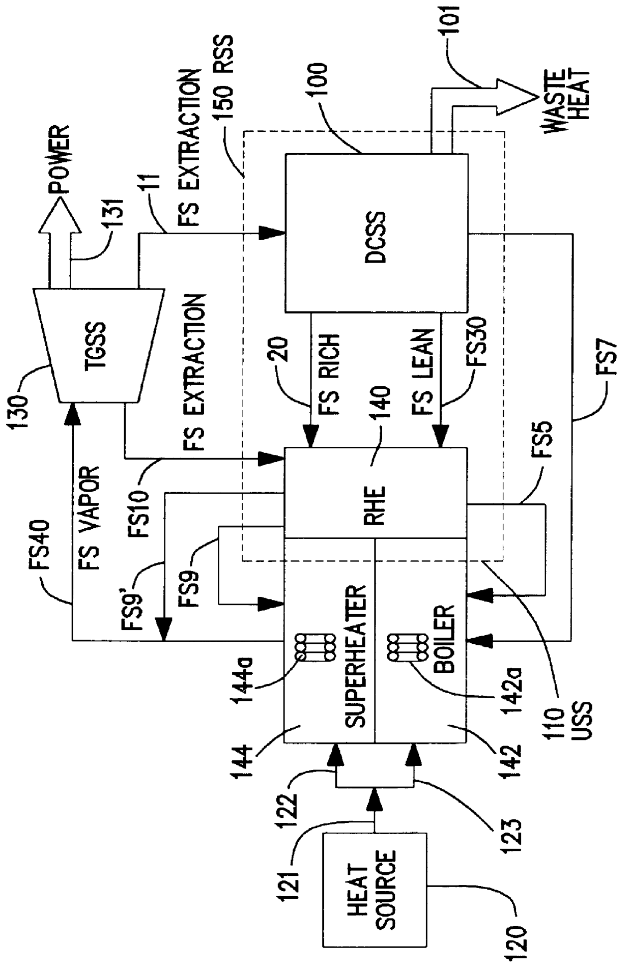
time frame to avoid insufficient working fluid flows within the system, e.g., insufficient superheated vapor FS 40 being, provided to the TGSS 130 and / or insufficient feed fluid 57 being provided to the boiler tubes 142a.
Accordingly, problems may arise in the operation of conventional self balancing Kalina cycle power generation systems when subjected to conditions which occasionally occur in the operation of commercially implemented power generation systems.
Although the heat balances may be satisfactory under limited operating and environmental conditions with the system operating in a
constant pressure mode, under sliding pressure conditions various system anomalies are likely to occur.
For example, the heat exchanges in the exchangers 140a-140c may cause too much or too little heat to be transferred to certain flows and could even result in
stream FS 5 being vaporized causing system
instability, particularly in the drum
type system of FIG. 5B.
As mentioned above, conventional Kalina cycle power generation systems are designed as
constant pressure self--balancing systems, and hence lack
active control of the fluid flows within the system.
However, as also previously noted, while this may be satisfactory under test conditions, in a commercial
operating environment power generation systems occasionally encounter conditions which are outside of the system design specifications.
Such conditions are likely to make it difficult if not impossible for conventional Kalina power generation systems to accomplish the necessary self balancing in the required
time frame to avoid operational problems.

