Electrical contact system

a contact system and electrical contact technology, applied in the direction of contacts, coupling device connections, instruments, etc., can solve the problems of cumbersome electrical connection between the electrical contact system and the pressure sensor, complex and therefore time-consuming and expensive, etc., to achieve easy deflection or folding, high flexibility, and simplified structure

Inactive Publication Date: 2000-08-22
DIESSNER CARMEN
View PDF14 Cites 56 Cited by
  • Summary
  • Abstract
  • Description
  • Claims
  • Application Information

AI Technical Summary

Benefits of technology

The contact areas that correspond to the four pressure sensors are advantageously provided in the area of bendable, loop-like segments of the circuit board, with each bendable area extending along the loop-like segment. Such a loop-like segment has a high flexibility so that the contact area provided at that location can very easily be

Problems solved by technology

Producing the electrical connection between the electrical contact system and the

Method used


Image

  • Electrical contact system
  • Electrical contact system
  • Electrical contact system

Examples


Embodiment Construction

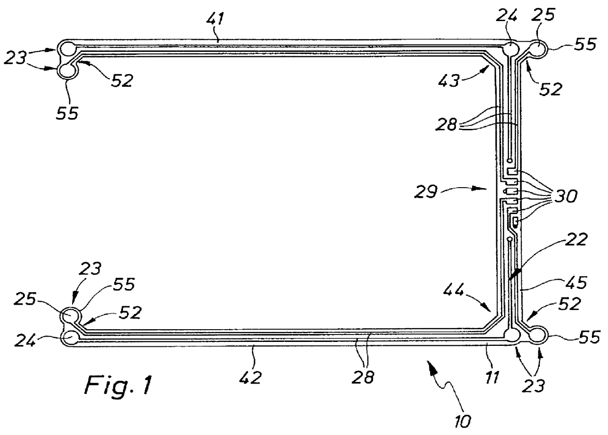
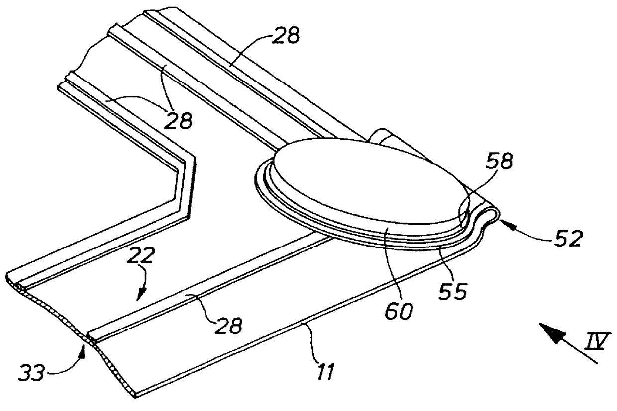
FIGS. 1-6 illustrate a first embodiment of the electrical contact system 10 according to the invention comprising a flexible circuit board 11, which may, for example, be U-shaped. The electrical contact system 10 serves to contact at least one electrical component 12, or pressure sensor 19 from different contact sides 13, 14 (see FIG. 4).

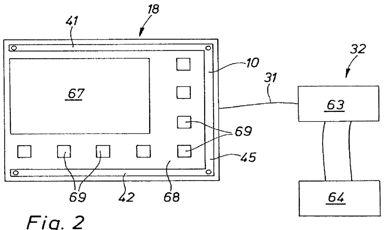
In the preferred embodiment, the electrical contact system represents the component of a touch panel 18, as shown schematically in FIG. 2. To this effect, the electrical contact system 10 is designed to contact a plurality of pressure sensors 19 representing the electrical components 12.

The circuit board 11 has a component side 22, on which four groups 23 of two spaced-apart electrically conductive contact area 24, 25 are provided. Each group 23 of contact areas 24, 25 serves to contact one pressure sensor 19. Both the number of provided groups 23, as well as the number of provided contact areas 24, 25 per group may, of course, be varied based on th...


PUM


Abstract

What is disclosed is an electrical contact system (10) for four pressure sensors (19) to be electrically contacted from different contact sides (13, 14). For this purpose a component side (22) of a flexible circuit board (11) has spaced-apart contact areas (24, 25), which come into contact with opposite contact areas (48, 49) provided on the pressure sensors (19) by folding the circuit board (11) over in a bendable are (52) between two contact areas (24, 25) to provide for a quick and reliable contacting process.

Description

1. Technical Field of the InventionThe present invention relates to an electrical contact system, as a component of a touch panel, for four pressure sensors that are to be electrically contacted from different contact sides.2. Prior ArtThere are known electrical contact systems, for example for contacting a piezoelectric pressure sensor, wherein the pressure sensor is soldered from one of the contact sides to a contact area on the circuit board, or electrically connected to this contact area by some other known method. In the case of the pressure sensor, it is furthermore necessary to contact same from the contact side opposite the circuit board. This is accomplished with a short conductor, for example gold foil, which is soldered to the pressure sensor on one hand and to a corresponding conductor path on the circuit board on the other hand. To shield the established contacts in the area of the pressure sensor, it may furthermore be necessary to first apply an insulation layer and t...

Claims


Application Information

Patent Timeline
IPC IPC(8): H01R13/70H05K1/11G06F3/03G06F3/037H01R12/62H05K3/30
CPCH01R13/701H05K1/118H01R12/62H01H2229/038
Inventor DIESSNER, CARMEN
Owner DIESSNER CARMEN
Why Eureka
Try Eureka