Ink tank, head cartridge and ink jet printing apparatus

a printing apparatus and head cartridge technology, applied in printing and other directions, can solve the problems of difficult to completely remove foamed block films, large amount of residue practically adhering to each void, and inability to exhibit the function of absorbing ink

Inactive Publication Date: 2000-08-29
CANON KK
View PDF21 Cites 18 Cited by
  • Summary
  • Abstract
  • Description
  • Claims
  • Application Information

AI Technical Summary

Problems solved by technology

Thus, since the voids are isolated from each other due to the presence of the film between adjacent voids, the foamed block can not exhibit a function of absorbing ink therein as it is.
However, it is very difficult to completely remove films in the foamed block with the film removing treatment as mentioned above.
In most cases, a considerable amount of residue practically adheres to each void or pore on completion of the film removing treatment.
However, since film residues remaining between adjacent voids or pores are liable to overlap in the foamed block, there arise malfunctions that ink hardly flows in the ink absorbing member, and moreover, ink fails to be fed outside of the ink tank.
For this reason, there arises a problem that an attitude to be assumed at the time of practical use of the ink tank described in the official gazette is restrictively determined.
In addition, in the case that the ink absorbing member is accommodated in the ink tank in the preferably employable uncompressed state, it is difficult that the ink absorbing member is brought in close contact with the inner wall surface of the ink tank.
Thus, a gap is liable to appears between the ink absorbing member and the inner wall surface of the ink tank.
When the atmospheric air taken through an atmospheric air communication port or an ink ejecting port of an ink jet head stays in the gap, there arises a malfunction that as ink is ejected from the ink jet head, a bubble is involved in the ink fed to the ink jet head, causing a quality of printed image to be remarkably degraded.
Especially, with respect to an ink jet recording apparatus of the type including an ink tank and an ink jet head integrated with each other to perform a printing operation by reciprocably scanning the integrated structure composed of the ink tank and the ink jet head relative to a printing medium, there readily arises a problem that the ink tank is vibratively displaced due to the reciprocable scanning of the foregoing integrated structure.
In the case that the ink jet printing apparatus is adversely affected by the vibrative displacement of the ink tank or in the case that the ink tank includes a member at the position located in the vicinity of an ink outflow portion, when a part of the ink absorbing member located in the vicinity of the ink outflow portion exhibits deterioration in terms of properties as time elapses, a gap is liable to appear at the above-noted part of the ink absorbing member.
Once such a malfunction as mentioned above has arose, it becomes impossible to perform a desired ink ejecting operation, and moreover, the ink present in an ink feeding path leaks from an ink ejecting port, causing the interior of the

Method used


Image

  • Ink tank, head cartridge and ink jet printing apparatus
  • Ink tank, head cartridge and ink jet printing apparatus
  • Ink tank, head cartridge and ink jet printing apparatus

Examples


second embodiment

of Second Embodiment)

FIG. 7 is a perspective view of an ink tank constructed according to an embodiment modified from the second embodiment of the present invention, particularly showing the structure of the ink tank in the disassembled state.

Referring to FIG. 7, while a foamed block 232 molded of a melamine resin is accommodated in a housing 231, a dimension a2 of the foamed block 232 located remote from an ink feeding port 233 is determined to be smaller than a dimension a1 of the same located in the proximity of the same so that the foamed block 232 has a certain gradient across the length of the foamed block along the upper surface of the same between both the dimensions a1 and a2. With such construction, while the foamed block 232 is accommodated in the housing 233, a cell size of the foamed block 232 is distributed such that a number of cells are forcibly formed in such a manner as to allow the cell size to become smaller as the measuring position approaches toward the ink fee...

modified example 2

(Modified Example 2 of Second Embodiment 2)

FIG. 8 is a perspective view of an ink tank constructed according to another embodiment modified from the second embodiment of the present invention, particularly showing the structure of the ink tank in the disassembled state.

Referring to FIG. 8, the ink tank includes a foamed block 242 molded of a melamine resin and a housing 241 in which the foamed block 242 is accommodated, and a number of holes 247 each extending from an atmosphere communicating port 243 side toward an ink feeding port 246 side are formed through the foamed block 242 in the longitudinal direction. With this construction, lattices (composed of fibers) forming a number of cells in the foamed block 242 are separated from each other, causing a part of the foamed block 242 having an enlarged pore size to be forcibly formed.

Consequently, ink can stably be fed to a printing head 244 attached to the fore surface of the housing 241. The extension of each hole 247 from the atmos...

third embodiment

(Third Embodiment)

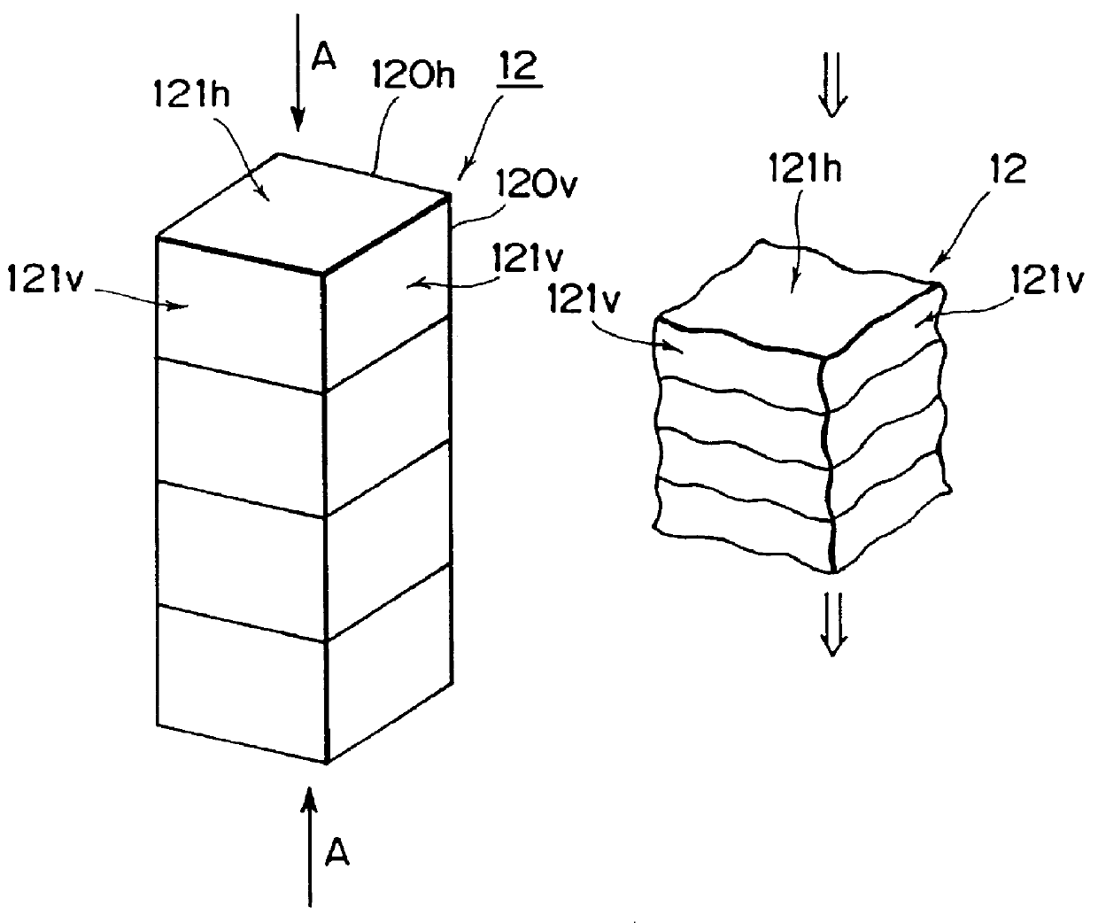
This embodiment is intended mainly to illustrate a forming process to be employed when holes and slits described above in the aforementioned embodiments modified from the second embodiment of the present invention are formed in an ink absorbing member molded of a melamine-formaldehyde condensate.

FIG. 11 shows by way of perspective view the structure of an ink absorbing member constructed according to a third embodiment of the present invention wherein a cutting operation and a hole forming operation are performed for the ink absorbing member by actuating a water jet cutter. In the drawing, reference numeral 301 designates an ink absorbing member, reference numeral 302 designates a plurality of holes each formed by actuating the water jet cutter, and reference numeral 310 designates a filter disposed at an ink outflow portion of the ink absorbing member 301. Incidentally, an ink tank, a housing and a printing head each associated with the ink absorbing member are no...


PUM


Abstract

A length of a melamine foamed block to be accommodated in an ink tank housing as measured in the longitudinal direction is dimensioned to be larger than a length of the ink tank housing as measured in the longitudinal direction. Thus, while the foamed block is accommodated in the ink tank housing, it is compressed in the direction orienting toward an ink feeding port from which ink is fed to a printing head, i.e., in the ink feeding direction. Consequently, the ink retaining force induced by the capillary force is not intensified in the compressing direction of the melamine foamed block, resulting in an ink feeding capability of the printing head being improved. On the contrary, the ink retaining force effective at a right angle relative to the compressing direction of the melamine foamed block is intensified.

Description

1. Field of the InventionThe present invention relates to an ink tank, a head cartridge including the ink tank and an ink jet head integrated with each other, and an ink jet printing apparatus including the ink tank and the head cartridge for performing a printing operation with them. More particularly, the present invention relates to the structure of the ink tank of the type having an ink absorbing member accommodated therein for the purpose of ink retaining.Here, the printing operation represents all type of operations each to be performed for a various kind of ink receiving medium such as a cloth, a thread, a paper, a sheet-like material or the like so as to allow ink to be adhesively secured thereto. Therefore, the present invention can be applied to a printing apparatus, i.e., a printer serving as an information outputting apparatus operatively associated with a various kind of information processing apparatus.2. Description of the Related ArtMany foamed blocks each molded of ...

Claims


Application Information

Patent Timeline
IPC IPC(8): B41J2/175
CPCB41J2/17513B41J2/1752B41J2/17553B41J2/17563
Inventor HIGUMA, MASAHIKOKAWAI, JUNSATO, YOHEITANEYA, YOICHISUGITANI, HIROSHIOHTA, TOKUYAMASUDA, KAZUAKIISHINAGA, HIROYUKIOSADA, TORACHIKASAITO, TAKASHI
Owner CANON KK
Why Eureka
Try Eureka