Method for deploying cuff prostheses

Inactive Publication Date: 2000-08-29
MEDTRONIC AVE
View PDF65 Cites 565 Cited by
  • Summary
  • Abstract
  • Description
  • Claims
  • Application Information

AI Technical Summary

Problems solved by technology

Preferably, any liner comprises a semi-permeable membrane or textile which allows for tissue ingrowth into

Method used


Image

  • Method for deploying cuff prostheses
  • Method for deploying cuff prostheses
  • Method for deploying cuff prostheses

Examples


Embodiment Construction

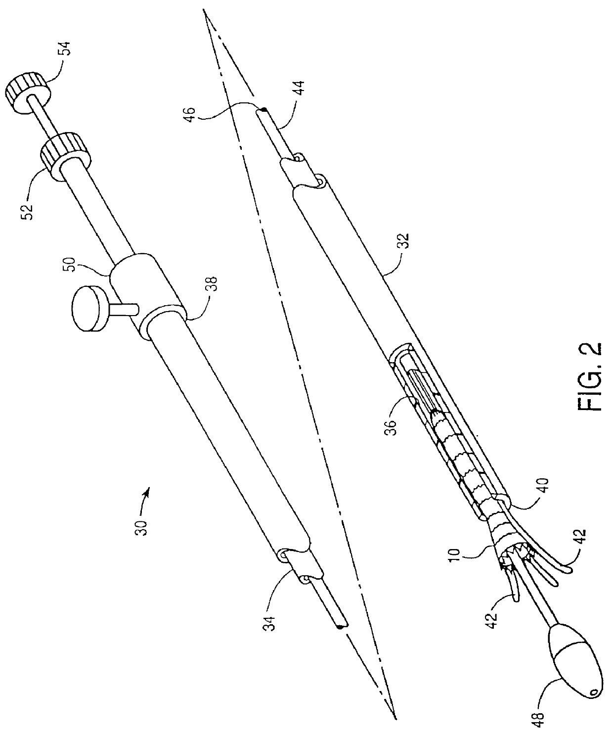
The present invention will find its greatest use as an endovascular prostheses for the treatment of diseases of the vasculature, particularly aneurysms, stenoses, and the like. The prostheses will generally be radially expandable from a narrow-diameter configuration to facilitate introduction into the body lumen, typically during surgical cutdown or percutaneous introduction procedures. Exemplary delivery catheters and methods for placement of the prostheses of the present invention are more fully described in co-pending U.S. patent application Ser. No. 08 / 475,200, (Attorney Docket No. 16380-11-3), the full disclosure of which is incorporated herein by reference.

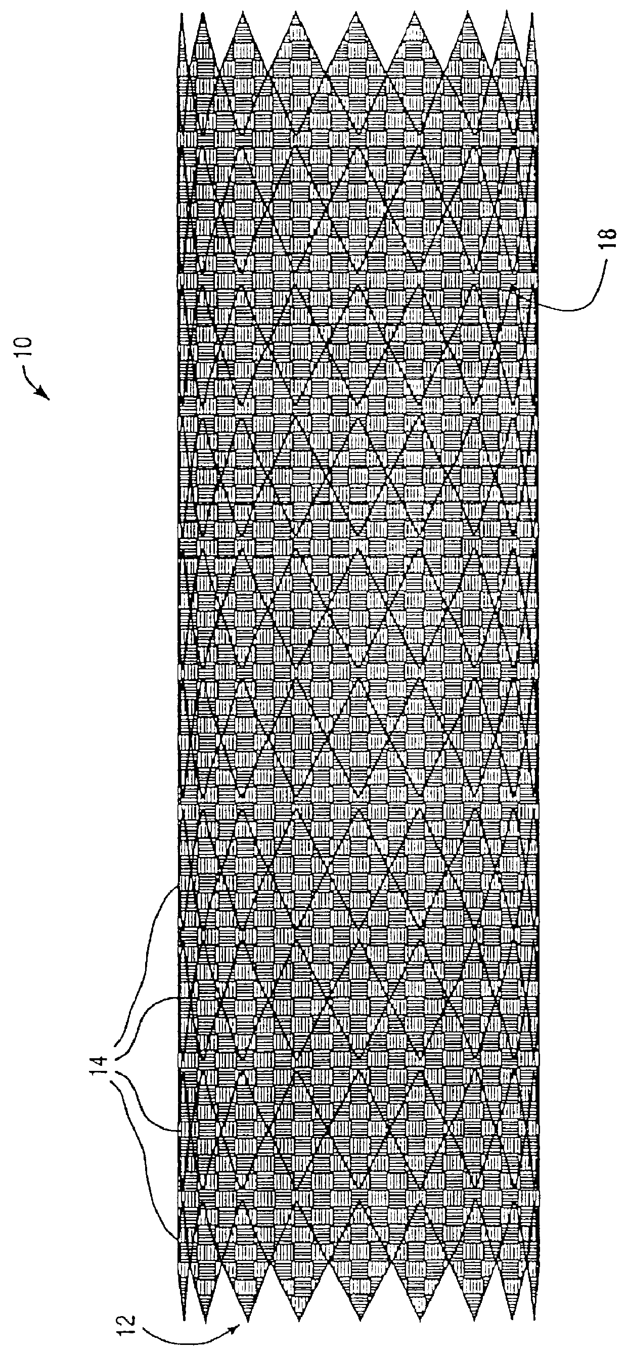
An exemplary cylindrical graft structure 10 is illustrated in FIG. 1. Prosthesis 10 comprises a perforate tubular frame 12 which includes a plurality of independent (non-connected) ring frames 14. The tubular frame 12 supports an inner liner 18. Optionally, an outer liner is disposed over the ring frames, either instead of i...


PUM


Abstract

The present invention provides modular intraluminal tubular prostheses, particularly stents and stent-grafts, for the treatment of disease conditions, particularly aneurysms. Modular sections of the prostheses, or "prosthetic modules," may be selectively combined to form a composite prosthesis having characteristics which are tailored to the specific requirements of the patient. Each prosthetic module preferably includes one or more standard interface ends for engaging another module, the module/module interface typically comprising ends which overlap and/or lock within a predetermined axial range. Advantageously, the axial length, cross-section, perimeter, resilient expansive force, axial flexibility, liner permeability, liner extensibility, radial conformability, liner/tubal wall sealing and anchoring, and other prosthetic characteristics may be varied along the axis of the composite prosthesis, and also along the axis of each prosthetic module. The modules are preferably individually introduced into a lumen system of a patient body so that the composite prosthesis is assembled in situ. Ideally, selection of appropriate prosthetic modules and the flexibility of the interface overlap range provides a custom fit intraluminal prosthesis which provides a therapy tailored to the individual patient's needs.

Description

1. Field of the InventionThe present invention relates generally to endoluminal tubular prostheses, such as stents, stent-grafts, and other structures. More particularly, the present invention provides modular tubular prosthesis structures having properties which can be tailored for individual body lumens, including blood vessels, particularly for the treatment of abdominal and other aneurysms.Vascular aneurysms are the result of abnormal dilation of a blood vessel, usually resulting from disease and / or genetic predisposition, which can weaken the arterial wall and allow it to expand. While aneurysms can occur in any blood vessel, most occur in the aorta and peripheral arteries, with the majority of aortic aneurysms occurring in the abdominal aorta, usually beginning below the renal arteries and often extending distally into one or both of the iliac arteries.Aortic aneurysms are most commonly treated in open surgical procedures where the diseased vessel segment is bypassed and repai...

Claims


Application Information

Patent Timeline
IPC IPC(8): A61F2/06A61F2/00A61F2/90
CPCA61F2/07A61F2/90A61F2/915A61F2/91A61F2002/065A61F2002/075A61F2002/30199A61F2002/30329A61F2002/91591A61F2220/0025A61F2230/0063Y10S623/902A61F2/89A61F2220/0075A61F2230/0054A61F2220/0016A61F2220/0041A61F2220/005A61F2220/0058A61F2220/0066A61F2230/0078
Inventor FOGARTY, THOMAS J.FREISLINGER, KIRSTENWEINBERG, STEVENCOX, BRIAN J.EVANS, MICHAEL A.KIM, STEVEN W.LENKER, JAY A.
Owner MEDTRONIC AVE
Why Eureka
Try Eureka