3-Stage fluidized bed reducing apparatus for reducing fine iron ore

Inactive Publication Date: 2000-08-29
POHANG IRON & STEEL CO LTD +2
View PDF7 Cites 29 Cited by
  • Summary
  • Abstract
  • Description
  • Claims
  • Application Information

AI Technical Summary

Problems solved by technology

However, in the case where a fine iron ore is to be reduced, if the superficial gas velocity is low as in the case of the fixed bed method, a sticking phenomenon occurs and the operation will finally be interrupted.
If these are to be achieved, the particle size of the raw iron ore has to be sternly limited.
Therefore, there is a problem that a wide distribution of particle sizes cannot be accommodated.
Consequently, the productivity becomes lower and additional process and facilities for screening and crushing are needed, thereby

Method used


Image

  • 3-Stage fluidized bed reducing apparatus for reducing fine iron ore
  • 3-Stage fluidized bed reducing apparatus for reducing fine iron ore
  • 3-Stage fluidized bed reducing apparatus for reducing fine iron ore

Examples


Embodiment Construction

>

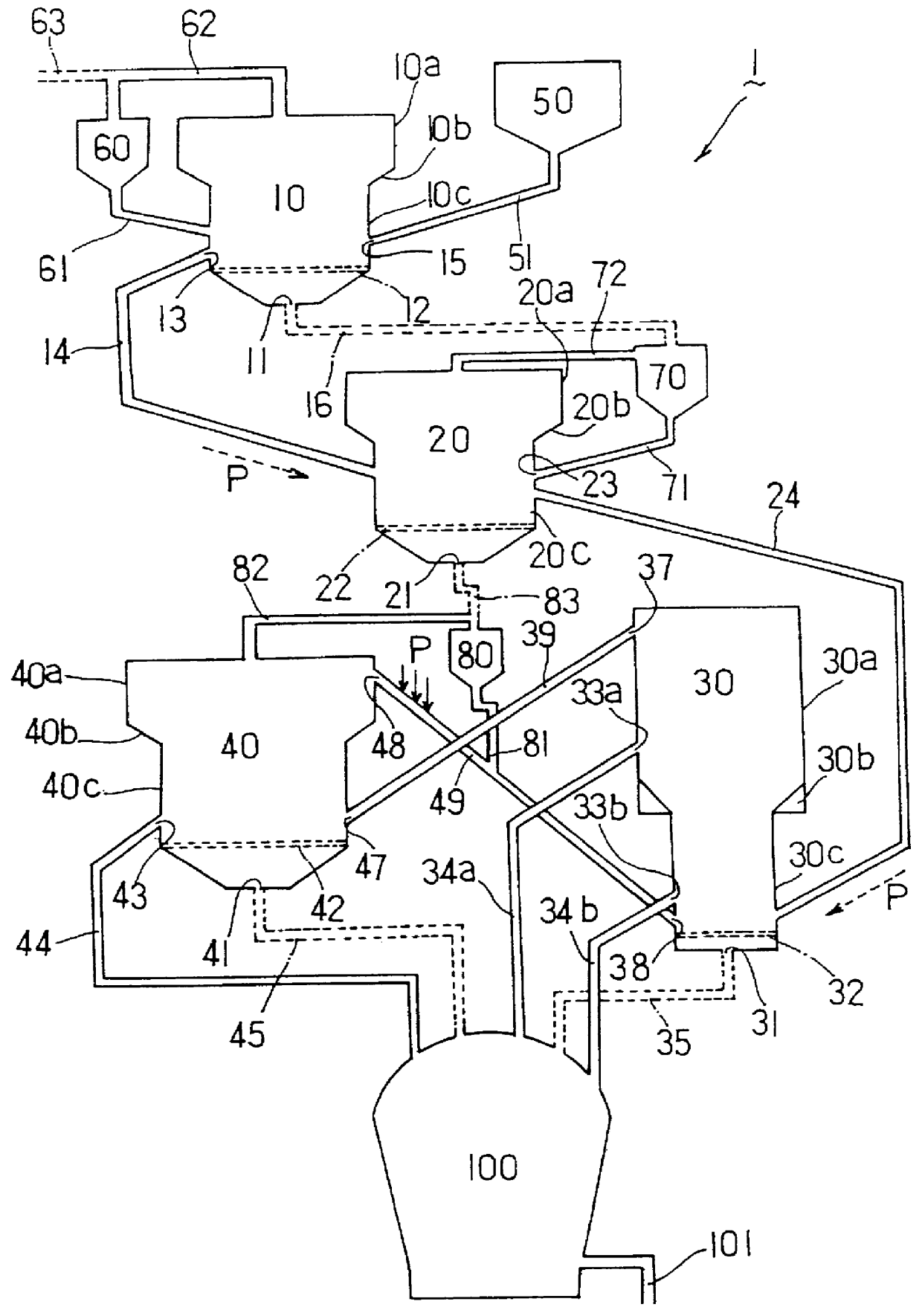
The reducing apparatus of FIG. 3 having the dimensions listed in Table 1 was constructed and the experiments were carried out under the conditions listed in Tables 2 to 4.

TABLE 2

TABLE 3

TABLE 4

The fine iron ore was reduced in the above described manner, and the average gas utilization degree and the gas consumption rate were evaluated. The result showed that the average gas utilization degree was 32%, and the gas consumption rate was 1230 Nm.sup.3 / ton-ore. Further, the average reduction degree of iron ores discharged from the third discharge hole, the fourth discharge hole and the fifth discharge hole were 88-95%. The ore discharge can be achieved within 60 minutes after feeding the ore from the hopper. That is, the average resident time in a reaction furnace was about 20 minutes, therefore it can be concluded that the production rate is excellent.

Further, the pre-reduced iron ore was supplied to the second reaction furnace in which the reduction was carried out by classifying the ...


PUM

PropertyMeasurementUnit
Fractionaaaaaaaaaa
Fractionaaaaaaaaaa
Fractionaaaaaaaaaa

Abstract

PCT No. PCT/KR97/00275 Sec. 371 Date Aug. 20, 1998 Sec. 102(e) Date Aug. 20, 1998 PCT Filed Dec. 19, 1997 PCT Pub. No. WO98/28449 PCT Pub. Date Jul. 2, 1998A 3-stage fluidized bed type iron ore reducing apparatus having X shaped circulating tubes is disclosed for forming a gas pore fluidizing layer of a fine iron ore, and for drying/pre-heating it to reduce it, so that the gas utilization rate and the reducing rate can be improved, as well as decreasing the gas consumption rate. The present invention relates to a 3-stage fluidized bed type iron ore reducing apparatus having X shaped circulating tubes comprising: a shaft type single type first fluidized bed furnace where a raw fine iron ore is dried and pre-heated in a bubbling fluidization state; a first cyclone for collecting fine iron ore particles from a exhaust gas of said first fluidized bed type furnace; a shaft type single type second fluidizing bed furnace where the dried and pre-heated fine iron ore is pre-reduced in a bubbling fluidization state; a second cyclone for separating the fine iron ore particles from a exhaust gas from said second fluidizing bed type furnace so as to re-circulate them; a twin type third fluidized bed furnace consisting of a first reaction furnace and a second reaction furnace, for separating the pre-reduced iron ore from said second fluidized bed type furnace into coarse particles and medium/fine particles so that the coarse particles and medium/fine particles ore finally reduced in separate reactors in bubbling fluidization states; and a third cyclone for separating fine iron ore particles from the exhaust gas of said second reaction furnace of said third fluidized bed type furnace so as to re-circulate them to said first reaction furnace.

Description

1. Field of the InventionThe present invention relates to a 3-stage fluidized bed fine iron ore reducing apparatus, in which a fine iron ore having a wide particle size distribution is reduced to a solid reduced iron within 3-stage fluidized bed furnaces in a stepwise manner before being put into a melting furnace. Particularly, the present invention relates to a 3-stage fluidized bed reducing apparatus in which the gas utilization rate and the reduction rate are improved.2. Description of the Prior ArtIn the conventional blast furnace, iron ore can be reduced based on the fixed bed method, because the solid particles have large sizes. However, in the case where a fine iron ore is to be reduced, if the superficial gas velocity is low as in the case of the fixed bed method, a sticking phenomenon occurs and the operation will finally be interrupted. Therefore, in this case, a fluidized bed method, in which the gas velocity is relatively high so as to make the movements of solid partic...

Claims


Application Information

Patent Timeline
IPC IPC(8): C21B13/14C21B13/02C21B13/00F27B15/00
CPCC21B13/002C21B13/14C21B2100/44C21B2100/66Y02P10/134Y02P10/20C21B13/02
Inventor JUNG, UOO CHANGCHOI, NAG JOONKANG, HEUNG WONKIM, HANG GOO
Owner POHANG IRON & STEEL CO LTD
Why Eureka
Try Eureka