Because of such a
delay, not only does the
sequence control require confirmation of the operation, but also difficulty is involved in installing and setting up limit switches required to accomplish confirmation of the operation.
In the case of the grinding machine such as shown in FIG. 7, about ten different operations take place and, therefore, even though a delay of individual controllers may be minimal, accumulation of those delays brought about by those controllers would be detrimental.
In the case of an AC
relay or the like, a delay may result from the power source frequency.
Even in the case of a DC
relay, a delay of some tens of msec. may result.
Although variable subject to the sequencer and the method of compiling its program, a delay of a few msec. or larger may result.
Although variable subject to the length of the
piping system, the rigidity of pipes and the difference in hydraulic or
pneumatic pressure, a delay of some tens of msec. or larger may result.
Though attempts have hitherto been made to employ a
servo valve for the hydraulic valve, the delay in the basic
sequential control could not be removed.
However, what is provided with a
servo system is only the
loader arm which requires force, and even the hydraulic
servo system requires a delay of some tens of msec. or large before it starts its operation.
For this reason, no accurate evaluation of the grindstone sharpness is possible.
In particular, where the
cutting control to be employed during the finishing process or the like is to be tailored, no stable control is possible unless the accurate grindstone sharpness is obtained.
However, with these amounts of the bite retraction, the cycle tends to become unstable if the speed of
cutting during the finishing process is decreased and / or the power set during the finishing process is lowered, accompanied by considerable variation in time required to accomplish the finishing process.
Also, even in the case where the sharpness of the grindstone such as a CBN grindstone tends to vary considerably before and after dressing and / or the
processing allowance tends to vary, the cycle tends to become unstable.
However, in performing the control by the utilization of the amount of the bite retraction Xbo so calculated, there is a third problem in that no NC device is available which has a capability of changing the amount of the bite retraction during the
cutting.
Also, since the finishing process is predicated to achieve the control during the rough processing, a delay in the
control system and also in the
mechanical system poses a considerable problem.
The second problem is associated with the manner by which the grindstone sharpness during the processing is determined.
However, at this time, there is a fourth problem in which a delay may occur in the cutting system.
Although variation may be small, it is a composite delay in which a delay in the
mechanical system and a delay in the electric system are combined.
Also, change in grinding time constants is an addition and an unstable phenomenon of the grinding cycle such as, for example, variation in length of time required to accomplish the finishing may occur.
The efficiency of the rough processing is related to the magnitude of wear or separation of the grindstone and is limited to a range in which deterioration of the
processing accuracy is minimal.
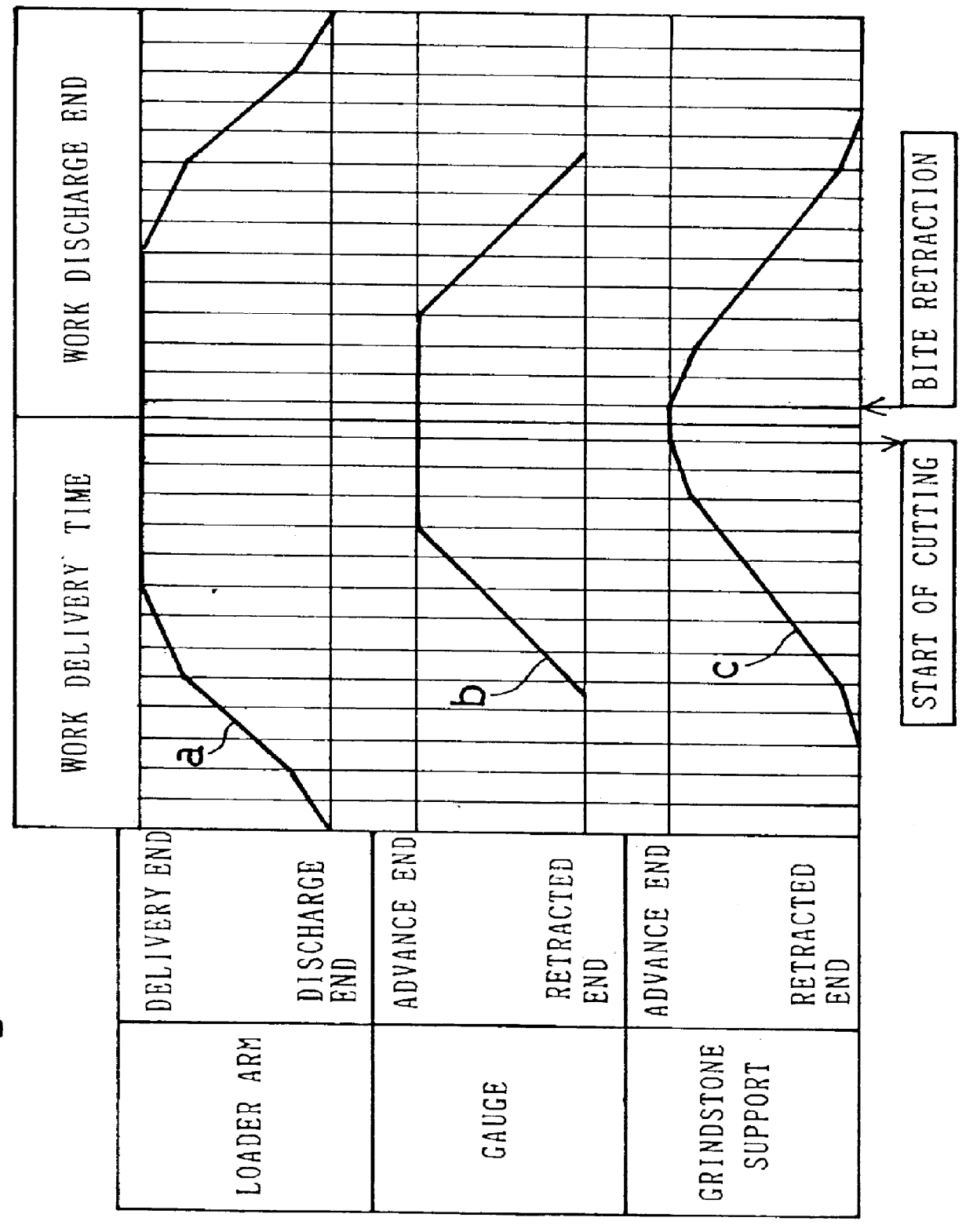
However, before the cutting speed changes, a delay corresponding to the time t1 during which the rough grinding takes place and the time t2 during which it stops until the bite retraction is initiated occurs.
If the delay in cutting is large and the finishing allowance g1 is reduced, it may occur that the finishing process cannot be executed.
Also, since a delay in cutting may occur at the time of termination of the finishing process, the
processing accuracy may be deteriorated if the processing resistance is high and / or if the work processing speed is high.
This tends to being about an unnecessary increase of the processing time.
In addition, although since the control of the bite retraction amount is carried out by predicating the finishing process during the rough processing, the delay in response of the
control system and the
mechanical system would
pose a detrimental problem, the processing with stabilized accuracy can be accomplished without the processing efficiency being lowered, by determining the bite retraction amount in consideration of the various delay.

